Protocol++® (Protocolpp®) is a software tool to be used standalone or in larger software projects to protect users’ data and communicate with other devices around the world. It contains several interfaces to allow a user to directly access encryption and authentication algorithms to obscure and authenticate data. The protocols can be used to create software stacks such that all levels of the network can be supported. The protocols and underlying engines can also be used in drivers to send and receive data on local and internet networks. Finally, Protocol++® provides a testbench interface to allow the protocols to be driven to a software ring to test a device-under-test (DUT) for compliance with the protocols standards supported by Protocol++®
Protocol++® Use Cases
Protocol++® (ProtocolPP®) can be used for several different use cases in development, software, hardware development, stacks, and testbenches.
- TESTBENCHES - Protocolpp® comes with a testbench to allow the interface to be connected to a Device Under Test (DUT) through software rings for test of protocols, encryption, and authentication algroithms, replay windows, randomization, Diffie-Hellman routines, and other items. In addition, Protocol++® can be used to generate XML output for all of the above items that can be read back in to drive Verilog or software drivers for development of hardware accelerators and software
- STACKS - The drivers in ProtocolPP® show examples of how to write software stacks that support all levels of the OSI model to allow full manipulation of all features and methodologies of the protocol stack. Want to try out a new retry routine for TCP? Change the code in level 4 of your software stack to try it out. Want to try a new algorithm for IPsec? Add it to level 3 of the stack. Developing a driver for extended packet numbers in Macsec? Run your software against the Protocol++® testbench to ensure conformance. Additional protocols that do not need need the stack and require direct access to level 3 (IP/IPsec) such as Real Time Protocol (RTP) or its secure version (SRTP)? Disable TCP/UDP and TLS to drive IP/IPsec directly
- HARDWARE DEVELOPMENT - Protocol++® can be used for testing hardware accelerators that support encryption and authentication algorithms. Developing an AES-GCM engine for your hard drive controller? Instantiate AES-GCM using the "ciphers" interface of ProtocolPP® in your SystemC testbench to driver your Verilog or VHDL through your UVM driver. Received your silicon back from manufacting and need to verify there are no defects? Read back in the XML files generated during pre-silicon testing that achieves 100% coverage, and execute them through the ProtocolPP® driver (or your own driver) and compare to the expected value. Have some conformance vectors from the specification? Enter the conformance data into the XML format specified by the Protocol++® XML schema, read the data into the testbench or driver, and test the silicon and or RTL
- SOFTWARE - The elements of ProtocolPP® can be incorporated into larger software projects to encrypt data, authenticate, generate CRC32 values, create Signatures, verify signatures, create PRF material, generate random data over ranges as bytes, words, or double words, enable SMFT mode and generate millions of random bytes from hardware is little or no time
These are the use cases currently being used. Development continues for Internet Key Exchange (IKEv2), additional driver features (ICMP message generation and return), offline key protection, key ring use, etc.
Please see the documentation found above and www.protocolpp.com for all options
Ciphers Interface
When using Protocol++® ciphers and authentication algorithms, the interface found in the ProtocolPP::ciphers and ProtocolPP::jmodes classes allows access to all the engines used. There is support for the following ciphers and modes:
| CBC | CTR | CCM | GCM | XTS | CMAC | GMAC | XCBC-MAC | AEAD | STREAM | |
|---|---|---|---|---|---|---|---|---|---|---|
| AES | X | X | X | X | X | X | X | X | - | - |
| SERPENT | X | X | X | X | - | X | X | X | - | - |
| DES | X | - | - | - | - | - | - | - | - | - |
| CAMELLIA | X | X | X | X | - | - | - | - | - | - |
| SEED | X | X | - | - | - | - | - | - | - | - |
| ARIA | X | X | X | X | - | - | - | - | - | - |
| SM4 | X | X | X | X | - | - | - | - | - | - |
| CHACHA20 | - | - | - | - | - | - | - | - | X | X |
| SNOW3G | - | - | - | - | - | - | - | - | - | X |
| SNOWV | - | - | - | X | - | - | - | - | - | X |
| ZUC | - | - | - | - | - | - | - | - | - | X |
| ZUC256 | - | - | - | - | - | - | - | - | - | X |
Authentication is provided with the following algorithms
| Auth Algorithm | ICV Length | |||||||||
|---|---|---|---|---|---|---|---|---|---|---|
| 4 | 8 | 10 | 12 | 16 | 20 | 24 | 32 | 48 | 64 | |
| MD5 | - | X | X | X | X | - | - | - | - | - |
| SHA1 | - | X | X | X | X | X | - | - | - | - |
| SHA224 | - | X | - | X | X | X | X | - | - | - |
| SHA256 | - | X | - | X | X | X | X | X | - | - |
| SHA384 | - | X | - | X | X | X | X | X | X | - |
| SHA512 | - | X | - | X | X | X | X | X | X | X |
| SHA3-224 | - | X | - | X | X | X | X | - | - | - |
| SHA3-256 | - | X | - | X | X | X | X | X | - | - |
| SHA3-384 | - | X | - | X | X | X | X | X | X | - |
| SHA3-512 | - | X | - | X | X | X | X | X | X | X |
| SHAKE128 | X | X | X | X | X | X | X | X | X | X |
| SHAKE256 | X | X | X | X | X | X | X | X | X | X |
| HMAC-MD5 | - | X | X | X | X | - | - | - | - | - |
| HMAC-SHA1 | - | X | X | X | X | X | - | - | - | - |
| HMAC-SHA2-224 | - | X | - | X | X | X | X | - | - | - |
| HMAC-SHA2-256 | - | X | - | X | X | X | X | X | - | - |
| HMAC-SHA2-384 | - | X | - | X | X | X | X | X | X | - |
| HMAC-SHA2-512 | - | X | - | X | X | X | X | X | X | X |
| HMAC-SHA3-224 | - | X | - | X | X | X | X | - | - | - |
| HMAC-SHA3-256 | - | X | - | X | X | X | X | X | - | - |
| HMAC-SHA3-384 | - | X | - | X | X | X | X | X | X | - |
| HMAC-SHA3-512 | - | X | - | X | X | X | X | X | X | X |
| POLY1305 | - | X | - | X | X | - | - | - | - | - |
| SM3 | - | X | - | X | X | - | - | - | - | - |
| SNOW3G | X | - | - | - | - | - | - | - | - | - |
| SNOWV | X | X | - | - | X | - | - | - | - | - |
| ZUC | X | - | - | - | - | - | - | - | - | - |
| ZUC256 | X | X | - | - | X | - | - | - | - | - |
In addition, CRC support is provided for CRC32-IEEE
Usage Example CHACHA20-Poly1305 Encryption
To use the CHACHA20 cipher, the ciphers interface would be called with the appropriate parameters. Because CHACHA20 is a STREAM cipher (there’s no direction in processing), direction is ignored, but STREAM must be passsed with the key and initial value. Protocol++® will return a shared pointer to the engine as shown
Usage Example SHA3-256 Authentication
To use the SHA3-256 authentication algorithm, the ciphers interface would be called with the authentication algorithm and the authentication key as shown below
For API Documentation:
- See also
- ProtocolPP::jmodes
- ProtocolPP::ciphers
- ProtocolPP::jconfident
- ProtocolPP::jconfidentsa
- ProtocolPP::jintegrity
- ProtocolPP::jintegritysa
For Additional Documentation:
ProtocolPP® Interface
Use of the protocols found in Protocol++® is accomplished by the code found in ProtocolPP::jprotocolpp. See the individual protocol sections found below for brief descriptions of the protocol and see the individual classes for full documentation of the features supported
Usage Example for IPsec Decapsulation
In this example, it is assumed that the parameters necessary for the IPsec flow have been negotiated by the endpoints. Depending on the protocol, this may be accomplished either by the IKEPRF protocol or the TLSPRF protocol using Diffie-Hellman or RSA for the key generation and negotiation. It is also assumed that the user has provided a cryptographically secure random data generator for padding, IV, and TFC padding creation (in the case of ENCAP when requested by the security parameters found in the security association
For API Documentation:
- See also
- ProtocolPP::jprotocolpp
DriverPP Interface
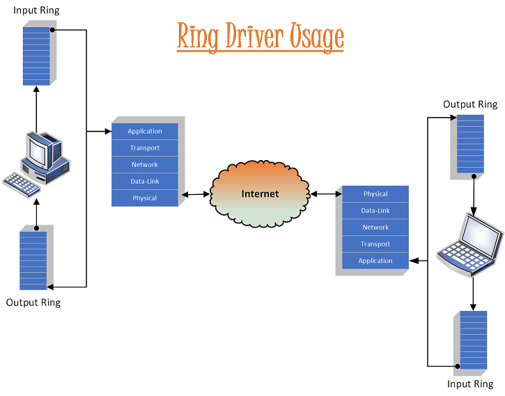
As mentioned previously, Protocolpp® (Protocol++®) can be used for software stacks to communitcate on networks and across the Internet. To facilitate this, Protocol++® contains drivers of different types to send and receive data from your application. Applications setup the driver with the IP address or host name they want to communicate with and the interfaces desired. If TLS is requested for the application level, TCP is used in the Transport level to assure delivery. SRTP uses UDP for best effort delivery to the endpoint. Access is provided to the Transport level for direct access to TCP and UDP. The user is able to select data assurance at the Network Layer by chosing ESPv4 or ESPv6 otherwise IPv4 or IPv6 can be selected. Data-Link Layer interfaces can select ethernet (Macsec), Wifi, WiMax, or LTE. LTE selection inserts RLC before/after LTE encapsulation and decapsulation (see LTE stack diagram in ProtocolPP::jlte)
Ring Driver
For API Documentation:
For Additional Documentation:
- See also
- jdrive
- jringdrive
- jdirectdrive
User Datagram Protocol (UDP)
(See https://en.wikipedia.org/wiki/User_Datagram_Protocol)
The User Datagram Protocol (UDP) is one of the core members of the Internet protocol suite. The protocol was designed by David P. Reed in 1980 and formally defined in RFC 768.
UDP uses a simple connectionless transmission model with a minimum of protocol mechanism. It has no handshaking dialogues, and thus exposes the user's program to any unreliability of the underlying network protocol. There is no guarantee of delivery, ordering, or duplicate protection. UDP provides checksums for data integrity, and port numbers for addressing different functions at the source and destination of the datagram.
With UDP, computer applications can send messages, in this case referred to as datagrams, to other hosts on an Internet Protocol (IP) network without prior communications to set up special transmission channels or data paths. UDP is suitable for purposes where error checking and correction is either not necessary or is performed in the application, avoiding the overhead of such processing at the network interface level. Time-sensitive applications often use UDP because dropping packets is preferable to waiting for delayed packets, which may not be an option in a real-time system. If error correction facilities are needed at the network interface level, an application may use the Transmission Control Protocol (TCP) or Stream Control Transmission Protocol (SCTP) which are designed for this purpose.
Attributes
A number of UDP's attributes make it especially suited for certain applications
- It is transaction-oriented, suitable for simple query-response protocols such as the Domain Name System or the Network Time Protocol.
- It provides datagrams, suitable for modeling other protocols such as in IP tunneling or Remote Procedure Call and the Network File System.
- It is simple, suitable for bootstrapping or other purposes without a full protocol stack, such as the DHCP and Trivial File Transfer Protocol.
- It is stateless, suitable for very large numbers of clients, such as in streaming media applications for example IPTV
- The lack of retransmission delays makes it suitable for real-time applications such as Voice over IP, online games, and many protocols built on top of the Real Time Streaming Protocol.
- Works well in unidirectional communication, suitable for broadcast information such as in many kinds of service discovery and shared information such as broadcast time or Routing Information Protocol
Reliability and congestion control solutions
Lacking reliability, UDP applications must generally be willing to accept some loss, errors or duplication. Some applications, such as TFTP, may add rudimentary reliability mechanisms into the application layer as needed
Most often, UDP applications do not employ reliability mechanisms and may even be hindered by them. Streaming media, real-time multiplayer games and voice over IP (VoIP) are examples of applications that often use UDP. In these particular applications, loss of packets is not usually a fatal problem. If an application requires a high degree of reliability, a protocol such as the Transmission Control Protocol may be used instead.
In VoIP, for example, latency and jitter are the primary concerns. The use of TCP would cause jitter if any packets were lost as TCP does not provide subsequent data to the application while it is requesting re-sending of the missing data. If using UDP the end user applications must provide any necessary handshaking such as real time confirmation that the message has been received.
Applications
Numerous key Internet applications use UDP, including: the Domain Name System (DNS), where queries must be fast and only consist of a single request followed by a single reply packet, the Simple Network Management Protocol (SNMP), the Routing Information Protocol (RIP) and the Dynamic Host Configuration Protocol (DHCP).
Voice and video traffic is generally transmitted using UDP. Real-time video and audio streaming protocols are designed to handle occasional lost packets, so only slight degradation in quality occurs, rather than large delays if lost packets were retransmitted. Because both TCP and UDP run over the same network, many businesses are finding that a recent increase in UDP traffic from these real-time applications is hindering the performance of applications using TCP, such as point of sale, accounting, and database systems. When TCP detects packet loss, it will throttle back its data rate usage. Since both real-time and business applications are important to businesses, developing quality of service solutions is seen as crucial by some
Some VPN systems such as OpenVPN may use UDP while implementing reliable connections and error checking at the application level.
Virtual eXtensible Local Area Network (VXLAN)
See RFC7348 for full details
Current Layer 2 networks use the IEEE 802.1D Spanning Tree Protocol (STP) to avoid loops in the network due to duplicate paths. STP blocks the use of links to avoid the replication and looping of frames. Some data center operators see this as a problem with Layer 2 networks in general, since with STP they are effectively paying for more ports and links than they can really use. In addition, resiliency due to multipathing is not available with the STP model
Newer initiatives, such as TRILL [RFC6325] and SPB [802.1aq], have been proposed to help with multipathing and surmount some of the problems with STP. STP limitations may also be avoided by configuring servers within a rack to be on the same Layer 3 network, with switching happening at Layer 3 both within the rack and between racks. However, this is incompatible with a Layer 2 model for inter-VM communication
A key characteristic of Layer 2 data center networks is their use of Virtual LANs (VLANs) to provide broadcast isolation. A 12-bit VLAN ID is used in the Ethernet data frames to divide the larger Layer 2 network into multiple broadcast domains. This has served well for many data centers that require fewer than 4094 VLANs. With the growing adoption of virtualization, this upper limit is seeing pressure. Moreover, due to STP, several data centers limit the number of VLANs that could be used. In addition, requirements for multi-tenant environments accelerate the need for larger VLAN limits
For the Protocol++® interface to UDP and VXLAN see
For API Documentation:
For Additional Documentation:
Transport Control Protocol (TCP)
(See https://en.wikipedia.org/wiki/Transmission_Control_Protocol)
The Transmission Control Protocol (TCP) is a core protocol of the Internet protocol suite. It originated in the initial network implementation in which it complemented the Internet Protocol (IP). Therefore, the entire suite is commonly referred to as TCP/IP. TCP provides reliable, ordered, and error-checked delivery of a stream of octets between applications running on hosts communicating over an IP network. Major Internet applications such as the World Wide Web, email, remote administration and file transfer rely on TCP. Applications that do not require reliable data stream service may use the User Datagram Protocol (UDP), which provides a connectionless datagram service that emphasizes reduced latency over reliability.
Historical origin
In May 1974, the Institute of Electrical and Electronic Engineers (IEEE) published a paper titled "A Protocol for Packet Network Intercommunication." The paper's authors, Vint Cerf and Bob Kahn, described an internetworking protocol for sharing resources using packet-switching among the nodes. A central control component of this model was the Transmission Control Program that incorporated both connection-oriented links and datagram services between hosts. The monolithic Transmission Control Program was later divided into a modular architecture consisting of the Transmission Control Protocol at the connection-oriented layer and the Internet Protocol at the internetworking (datagram) layer. The model became known informally as TCP/IP, although formally it was henceforth called the Internet Protocol Suite.
Network function
The Transmission Control Protocol provides a communication service at an intermediate level between an application program and the Internet Protocol. It provides host-to-host connectivity at the Transport Layer of the Internet model. An application does not need to know the particular mechanisms for sending data via a link to another host, such as the required packet fragmentation on the transmission medium. At the transport layer, the protocol handles all handshaking and transmission details and presents an abstraction of the network connection to the application.
At the lower levels of the protocol stack, due to network congestion, traffic load balancing, or other unpredictable network behavior, IP packets may be lost, duplicated, or delivered out of order. TCP detects these problems, requests retransmission of lost data, rearranges out-of-order data, and even helps minimize network congestion to reduce the occurrence of the other problems. If the data still remains undelivered, its source is notified of this failure. Once the TCP receiver has reassembled the sequence of octets originally transmitted, it passes them to the receiving application. Thus, TCP abstracts the application's communication from the underlying networking details.
TCP is utilized extensively by many popular applications carried on the Internet, including the World Wide Web (WWW), E-mail, File Transfer Protocol, Secure Shell, peer-to-peer file sharing, and many streaming media applications.
TCP is optimized for accurate delivery rather than timely delivery, and therefore, TCP sometimes incurs relatively long delays (on the order of seconds) while waiting for out-of-order messages or retransmissions of lost messages. It is not particularly suitable for real-time applications such as Voice over IP. For such applications, protocols like the Real-time Transport Protocol (RTP) running over the User Datagram Protocol (UDP) are usually recommended instead.
TCP is a reliable stream delivery service which guarantees that all bytes received will be identical with bytes sent and in the correct order. Since packet transfer over many networks is not reliable, a technique known as positive acknowledgment with retransmission is used to guarantee reliability of packet transfers. This fundamental technique requires the receiver to respond with an acknowledgment message as it receives the data. The sender keeps a record of each packet it sends. The sender also maintains a timer from when the packet was sent, and retransmits a packet if the timer expires before the message has been acknowledged. The timer is needed in case a packet gets lost or corrupted
While IP handles actual delivery of the data, TCP keeps track of the individual units of data transmission, called segments, that a message is divided into for efficient routing through the network. For example, when an HTML file is sent from a web server, the TCP software layer of that server divides the sequence of octets of the file into segments and forwards them individually to the IP software layer (Internet Layer). The Internet Layer encapsulates each TCP segment into an IP packet by adding a header that includes (among other data) the destination IP address. When the client program on the destination computer receives them, the TCP layer (Transport Layer) reassembles the individual segments, and ensures they are correctly ordered and error free as it streams them to an application.
For the Protocol++® interface to TCP see
For API Documentation:
For Additional Documentation:
General Encapsulation Protocol (GRE)
See RFC2890, RFC2784, and RFC9187 for full details
Generic Routing Encapsulation (GRE) specifies a protocol for encapsulation of an arbitrary protocol over another arbitrary network layer protocol. This document describes extensions by which three fields, Checksum, Key, and Sequence Number, can be optionally carried in the GRE Header
Network Virtualization Using Generic Routing Encapsulation (NVGRE)
See RFC7637 for full details
Conventional data center network designs cater to largely static workloads and cause fragmentation of network and server capacity. There are several issues that limit dynamic allocation and consolidation of capacity. Layer 2 networks use the Rapid Spanning Tree Protocol (RSTP), which is designed to eliminate loops by blocking redundant paths. These eliminated paths translate to wasted capacity and a highly oversubscribed network. There are alternative approaches such as the Transparent Interconnection of Lots of Links (TRILL) that address this problem
The network utilization inefficiencies are exacerbated by network fragmentation due to the use of VLANs for broadcast isolation. VLANs are used for traffic management and also as the mechanism for providing security and performance isolation among services belonging to different tenants. The Layer 2 network is carved into smaller-sized subnets (typically, one subnet per VLAN), with VLAN tags configured on all the Layer 2 switches connected to server racks that host a given tenant’s services. The current VLAN limits theoretically allow for 4,000 such subnets to be created. The size of the broadcast domain is typically restricted due to the overhead of broadcast traffic. The 4,000-subnet limit on VLANs is no longer sufficient in a shared infrastructure servicing multiple tenants
For API Documentation:
For Additional Documentation:
Internet Control Message Protocol (ICMP)
See https://en.wikipedia.org/wiki/Internet_Control_Message_Protocol
See https://en.wikipedia.org/wiki/Internet_Control_Message_Protocol_version_6
The Internet Control Message Protocol (ICMP) is one of the main protocols of the internet protocol suite. It is used by network devices, like routers, to send error messages indicating, for example, that a requested service is not available or that a host or router could not be reached. ICMP can also be used to relay query messages.[1] It is assigned protocol number 1.[2] ICMP[3] differs from transport protocols such as TCP and UDP in that it is not typically used to exchange data between systems, nor is it regularly employed by end-user network applications (with the exception of some diagnostic tools like ping and traceroute)
For the Protocol++® interface to ICMP and ICMPv6 see
For API Documentation:
For API Documentation:
Internet Protocol (IP)
(See https://en.wikipedia.org/wiki/Internet_Protocol)
The Internet Protocol (IP) is the principal communications protocol in the Internet protocol suite for relaying datagrams across network boundaries. Its routing function enables internetworking, and essentially establishes the Internet.
IP has the task of delivering packets from the source host to the destination host solely based on the IP addresses in the packet headers. For this purpose, IP defines packet structures that encapsulate the data to be delivered. It also defines addressing methods that are used to label the datagram with source and destination information.
Historically, IP was the connectionless datagram service in the original Transmission Control Program introduced by Vint Cerf and Bob Kahn in 1974; the other being the connection-oriented Transmission Control Protocol (TCP). The Internet protocol suite is therefore often referred to as TCP/IP.
The first major version of IP, Internet Protocol Version 4 (IPv4), is the dominant protocol of the Internet. Its successor is Internet Protocol Version 6 (IPv6).
Function
The Internet Protocol is responsible for addressing hosts and for routing datagrams (packets) from a source host to a destination host across one or more IP networks. For this purpose, the Internet Protocol defines the format of packets and provides an addressing system that has two functions: Identifying hosts and providing a logical location service
Datagram construction
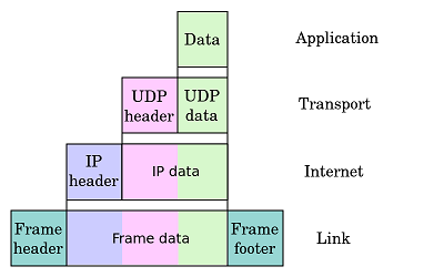
Each datagram has two components: a header and a payload. The IP header is tagged with the source IP address, the destination IP address, and other meta-data needed to route and deliver the datagram. The payload is the data that is transported. This method of nesting the data payload in a packet with a header is called encapsulation.
IP addressing and routing
IP addressing entails the assignment of IP addresses and associated parameters to host interfaces. The address space is divided into networks and subnetworks, involving the designation of network or routing prefixes. IP routing is performed by all hosts, as well as routers, whose main function is to transport packets across network boundaries. Routers communicate with one another via specially designed routing protocols, either interior gateway protocols or exterior gateway protocols, as needed for the topology of the network.
IP routing is also common in local networks. For example, many Ethernet switches support IP multicast operations. These switches use IP addresses and Internet Group Management Protocol to control multicast routing but use MAC addresses for the actual routing.
Reliability
The design of the Internet protocols is based on the end-to-end principle. The network infrastructure is considered inherently unreliable at any single network element or transmission medium and assumes that it is dynamic in terms of availability of links and nodes. No central monitoring or performance measurement facility exists that tracks or maintains the state of the network. For the benefit of reducing network complexity, the intelligence in the network is purposely located in the end nodes of data transmission. Routers in the transmission path forward packets to the next known, directly reachable gateway matching the routing prefix for the destination address.
As a consequence of this design, the Internet Protocol only provides best effort delivery and its service is characterized as unreliable. In network architectural language, it is a connectionless protocol, in contrast to connection-oriented modes of transmission. Various error conditions may occur, such as data corruption, packet loss, duplication and out-of-order delivery. Because routing is dynamic, meaning every packet is treated independently, and because the network maintains no state based on the path of prior packets, different packets may be routed to the same destination via different paths, resulting in out-of-order sequencing at the receiver.
Internet Protocol Version 4 (IPv4) provides safeguards to ensure that the IP packet header is error-free. A routing node calculates a checksum for a packet. If the checksum is bad, the routing node discards the packet. The routing node does not have to notify either end node, although the Internet Control Message Protocol (ICMP) allows such notification. By contrast, in order to increase performance, and since current link layer technology is assumed to provide sufficient error detection, the IPv6 header has no checksum to protect it.
All error conditions in the network must be detected and compensated by the end nodes of a transmission. The upper layer protocols of the Internet protocol suite are responsible for resolving reliability issues. For example, a host may cache network data to ensure correct ordering before the data is delivered to an application.
Link capacity and capability
The dynamic nature of the Internet and the diversity of its components provide no guarantee that any particular path is actually capable of, or suitable for, performing the data transmission requested, even if the path is available and reliable. One of the technical constraints is the size of data packets allowed on a given link. An application must assure that it uses proper transmission characteristics. Some of this responsibility lies also in the upper layer protocols. Facilities exist to examine the maximum transmission unit (MTU) size of the local link and Path MTU Discovery can be used for the entire projected path to the destination. The IPv4 internetworking layer has the capability to automatically fragment the original datagram into smaller units for transmission. In this case, IP provides re-ordering of fragments delivered out of order.
The Transmission Control Protocol (TCP) is an example of a protocol that adjusts its segment size to be smaller than the MTU. The User Datagram Protocol (UDP) and the Internet Control Message Protocol (ICMP) disregard MTU size, thereby forcing IP to fragment oversized datagrams.
Version history
The versions currently relevant are IPv4 and IPv6.
In May 1974, the Institute of Electrical and Electronic Engineers (IEEE) published a paper entitled "A Protocol for Packet Network Intercommunication".[6] The paper's authors, Vint Cerf and Bob Kahn, described an internetworking protocol for sharing resources using packet switching among network nodes. A central control component of this model was the "Transmission Control Program" that incorporated both connection-oriented links and datagram services between hosts. The monolithic Transmission Control Program was later divided into a modular architecture consisting of the Transmission Control Protocol at the transport layer and the Internet Protocol at the network layer. The model became known as the Department of Defense (DoD) Internet Model and Internet Protocol Suite, and informally as TCP/IP.
IP versions 0 to 3 were experimental versions, used between 1977 and 1979. The following Internet Experiment Note (IEN) documents describe versions of the Internet Protocol prior to the modern version of IPv4:
- IEN 2 (Comments on Internet Protocol and TCP), dated August 1977 describes the need to separate the TCP and Internet Protocol functionalities (which were previously combined.) It proposes the first version of the IP header, using 0 for the version field.
- IEN 26 (A Proposed New Internet Header Format), dated February 1978 describes a version of the IP header that uses a 1-bit version field.
- IEN 28 (Draft Internetwork Protocol Description Version 2), dated February 1978 describes IPv2.
- IEN 41 (Internetwork Protocol Specification Version 4), dated June 1978 describes the first protocol to be called IPv4. The IP header is different from the modern IPv4 header.
- IEN 44 (Latest Header Formats), dated June 1978 describes another version of IPv4, also with a header different from the modern IPv4 header.
- IEN 54 (Internetwork Protocol Specification Version 4), dated September 1978 is the first description of IPv4 using the header that would be standardized in RFC 760.
The dominant internetworking protocol in the Internet Layer in use today is IPv4; the number 4 is the protocol version number carried in every IP datagram. IPv4 is described in RFC 791 (1981).
Version 5 was used by the Internet Stream Protocol, an experimental streaming protocol.
The successor to IPv4 is IPv6. Its most prominent difference from version 4 is the size of the addresses. While IPv4 uses 32 bits for addressing, yielding c. 4.3 billion (4.3×10⁹) addresses, IPv6 uses 128-bit addresses providing ca. 340 undecillion, or 3.4×1038 addresses. Although adoption of IPv6 has been slow, as of June 2008, all United States government systems have demonstrated basic infrastructure support for IPv6. IPv6 was a result of several years of experimentation and dialog during which various protocol models were proposed, such as TP/IX (RFC 1475), PIP (RFC 1621) and TUBA (TCP and UDP with Bigger Addresses, RFC 1347).
The assignment of the new protocol as IPv6 was uncertain until due diligence revealed that IPv6 had not yet been used previously. Other protocol proposals named IPv9 and IPv8 briefly surfaced, but had no affiliation with any international standards body, and have had no support
Security
During the design phase of the ARPANET and the early Internet, the security aspects and needs of a public, international network could not be adequately anticipated. Consequently, many Internet protocols exhibited vulnerabilities highlighted by network attacks and later security assessments. In 2008, a thorough security assessment and proposed mitigation of problems was published. The Internet Engineering Task Force (IETF) has been pursuing further studies
For the Protocol++® interface to IP see
For API Documentation:
For Additional Documentation:
Transport Layer Security (TLS)
See https://en.wikipedia.org/wiki/Transport_Layer_Security
Transport Layer Security (TLS) and its predecessor, Secure Sockets Layer (SSL), both of which are frequently referred to as 'SSL', are cryptographic protocols that provide communications security over a computer network. Several versions of the protocols are in widespread use in applications such as web browsing, email, Internet faxing, instant messaging, and voice-over-IP (VoIP). Major web sites use TLS to secure all communications between their servers and web browsers
The primary goal of the Transport Layer Security protocol is to provide privacy and data integrity between two communicating computer applications. When secured by TLS, connections between a client (e.g., a web browser) and a server (e.g., wikipedia.org) have one or more of the following properties:
- The connection is private because symmetric cryptography is used to encrypt the data transmitted. The keys for this symmetric encryption are generated uniquely for each connection and are based on a shared secret negotiated at the start of the session (see TLS handshake protocol). The server and client negotiate the details of which encryption algorithm and cryptographic keys to use before the first byte of data is transmitted (see Algorithm). The negotiation of a shared secret is both secure (the negotiated secret is unavailable to eavesdroppers and cannot be obtained, even by an attacker who places himself in the middle of the connection) and reliable (no attacker can modify the communications during the negotiation without being detected)
- The identity of the communicating parties can be authenticated using public-key cryptography. This authentication can be made optional, but is generally required for at least one of the parties (typically the server)
- The connection is reliable because each message transmitted includes a message integrity check using a message authentication code to prevent undetected loss or alteration of the data during transmission
In addition to the properties above, careful configuration of TLS can provide additional privacy-related properties such as forward secrecy, ensuring that any future disclosure of encryption keys cannot be used to decrypt any TLS communications recorded in the past
TLS supports many different methods for exchanging keys, encrypting data, and authenticating message integrity (see Algorithm). As a result, secure configuration of TLS involves many configurable parameters, and not all choices provide all of the privacy-related properties described in the list above (see authentication and key exchange table, cipher security table, and data integrity table)
Attempts have been made to subvert aspects of the communications security that TLS seeks to provide and the protocol has been revised several times to address these security threats (see Security). Web browsers have also been revised by their developers to defend against potential security weaknesses after these were discovered (see TLS/SSL support history of web browsers.)
The TLS protocol is composed of two layers: the TLS record protocol and the TLS handshake protocol
TLS is a proposed Internet Engineering Task Force (IETF) standard, first defined in 1999 and updated in RFC 5246 (August 2008) and RFC 6176 (March 2011). It is based on the earlier SSL specifications (1994, 1995, 1996) developed by Netscape Communications for adding the HTTPS protocol to their Navigator web browser.
Description
Client-server applications use the TLS protocol to communicate across a network in a way designed to prevent eavesdropping and tampering
Since protocols can operate either with or without TLS (or SSL), it is necessary for the client to indicate to the server the setup of a TLS connection. There are two main ways of achieving this. One option is to use a different port number for TLS connections (for example, port 443 for HTTPS). The other is for the client to use a protocol-specific mechanism (for example, STARTTLS for mail and news protocols) to request that the server switch the connection to TLS
Once the client and server have agreed to use TLS, they negotiate a stateful connection by using a handshaking procedure. During this handshake, the client and server agree on various parameters used to establish the connection's security:
- The handshake begins when a client connects to a TLS-enabled server requesting a secure connection and presents a list of supported cipher suites (ciphers and hash functions)
- From this list, the server picks a cipher and hash function that it also supports and notifies the client of the decision
- The server usually then sends back its identification in the form of a digital certificate. The certificate contains the server name, the trusted certificate authority (CA) and the server's public encryption key
- The client confirms the validity of the certificate before proceeding
- To generate the session keys used for the secure connection, the client either:
- encrypts a random number with the server's public key and sends the result to the server (which only the server should be able to decrypt with its private key); both parties then use the random number to generate a unique session key for subsequent encryption and decryption of data during the session
- uses Diffie-Hellman key exchange to securely generate a random and unique session key for encryption and decryption that has the additional property of forward secrecy: if the server's private key is disclosed in future, it cannot be used to decrypt the current session, even if the session is intercepted and recorded by a third party.
This concludes the handshake and begins the secured connection, which is encrypted and decrypted with the session key until the connection closes. If any one of the above steps fail, the TLS handshake fails, and the connection is not created
TLS and SSL are defined as 'operating over some reliable transport layer', which places them as application layer protocols in the TCP/IP reference model and as presentation layer protocols in the OSI model. The protocols use a handshake with an asymmetric cipher to establish cipher settings and a shared key for a session; the rest of the communication is encrypted using a symmetric cipher and the session key
History and development
Secure Network Programming
Early research efforts towards transport layer security included the Secure Network Programming (SNP) application programming interface (API), which in 1993 explored the approach of having a secure transport layer API closely resembling Berkeley sockets, to facilitate retrofitting preexisting network applications with security measures
SSL 1.0, 2.0 and 3.0
Netscape developed the original SSL protocols. Version 1.0 was never publicly released because of serious security flaws in the protocol; version 2.0, released in February 1995, "contained a number of security flaws which ultimately led to the design of SSL version 3.0". Released in 1996, SSL version 3.0 represented a complete redesign of the protocol produced by Paul Kocher working with Netscape engineers Phil Karlton and Alan Freier, with a reference implementation by Christopher Allen and Tim Dierks of Consensus Development. Newer versions of SSL/TLS are based on SSL 3.0. The 1996 draft of SSL 3.0 was published by IETF as a historical document in RFC 6101
Dr. Taher Elgamal, chief scientist at Netscape Communications from 1995 to 1998, is recognized as the "father of SSL"
As of 2014 the 3.0 version of SSL is considered insecure as it is vulnerable to the POODLE attack that affects all block ciphers in SSL; and RC4, the only non-block cipher supported by SSL 3.0, is also feasibly broken as used in SSL 3.0
SSL 2.0 was deprecated (prohibited) in 2011 by RFC 6176
SSL 3.0 was deprecated in June 2015 by RFC 7568
TLS 1.0
TLS 1.0 was first defined in RFC 2246 in January 1999 as an upgrade of SSL Version 3.0, and written by Christopher Allen and Tim Dierks of Consensus Development. As stated in the RFC, "the differences between this protocol and SSL 3.0 are not dramatic, but they are significant enough to preclude interoperability between TLS 1.0 and SSL 3.0". TLS 1.0 does include a means by which a TLS implementation can downgrade the connection to SSL 3.0, thus weakening security
TLS 1.1
TLS 1.1 was defined in RFC 4346 in April 2006. It is an update from TLS version 1.0. Significant differences in this version include:
- Added protection against cipher-block chaining (CBC) attacks. The implicit initialization vector (IV) was replaced with an explicit IV
- Change in handling of padding errors
- Support for IANA registration of parameters
TLS 1.2
TLS 1.2 was defined in RFC 5246 in August 2008. It is based on the earlier TLS 1.1 specification. Major differences include:
- The MD5-SHA-1 combination in the pseudorandom function (PRF) was replaced with SHA-256, with an option to use cipher suite specified PRFs
- The MD5-SHA-1 combination in the finished message hash was replaced with SHA-256, with an option to use cipher suite specific hash algorithms. However the size of the hash in the finished message must still be at least 96 bits
- The MD5-SHA-1 combination in the digitally signed element was replaced with a single hash negotiated during handshake, which defaults to SHA-1
- Enhancement in the client's and server's ability to specify which hash and signature algorithms they accept
- Expansion of support for authenticated encryption ciphers, used mainly for Galois/Counter Mode (GCM) and CCM mode of Advanced Encryption Standard encryption
- TLS Extensions definition and Advanced Encryption Standard cipher suites were added
All TLS versions were further refined in RFC 6176 in March 2011 removing their backward compatibility with SSL such that TLS sessions never negotiate the use of Secure Sockets Layer (SSL) version 2.0
TLS 1.3 (draft)
As of January 2016, TLS 1.3 is a working draft, and details are provisional and incomplete. It is based on the earlier TLS 1.2 specification. Major differences from TLS 1.2 include:
- Removing support for weak and lesser used named elliptic curves (see Elliptic curve cryptography)
- Removing support for MD5 and SHA-224 cryptographic hash functions
- Requiring digital signatures even when a previous configuration is used
- Integrating HKDF and the semi-ephemeral DH proposal
- Replacing resumption with PSK and tickets
- Supporting 1-RTT handshakes and initial support for 0-RTT (see Round-trip delay time)
- Dropping support for many insecure or obsolete features including compression, renegotiation, non-AEAD ciphers, static RSA and static DH key exchange, custom DHE groups, point format negotiation, Change Cipher Spec protocol, Hello message UNIX time, and the length field AD input to AEAD ciphers
- Prohibiting SSL or RC4 negotiation for backwards compatibility
- Integrating use of session hash
- Deprecating use of the record layer version number and freezing the number for improved backwards compatibility
- Moving some security related algorithm details from an appendix to the specification and relegating ClientKeyShare to an appendix
- Adding of Curve25519 and Ed25519 to the TLS standard
Algorithm
Before a client and server can begin to exchange information protected by TLS, they must securely exchange or agree upon an encryption key and a cipher to use when encrypting data (see Cipher). Among the methods used for key exchange/agreement are: public and private keys generated with RSA (denoted TLS_RSA in the TLS handshake protocol), Diffie-Hellman (TLS_DH), ephemeral Diffie-Hellman (TLS_DHE), Elliptic Curve Diffie-Hellman (TLS_ECDH), ephemeral Elliptic Curve Diffie-Hellman (TLS_ECDHE), anonymous Diffie-Hellman (TLS_DH_anon), pre-shared key (TLS_PSK)[19] and Secure Remote Password (TLS_SRP)
The TLS_DH_anon and TLS_ECDH_anon key agreement methods do not authenticate the server or the user and hence are rarely used because those are vulnerable to Man-in-the-middle attack. Only TLS_DHE and TLS_ECDHE provide forward secrecy
Public key certificates used during exchange/agreement also vary in the size of the public/private encryption keys used during the exchange and hence the robustness of the security provided. In July 2013, Google announced that it would no longer use 1024 bit public keys and would switch instead to 2048 bit keys to increase the security of the TLS encryption it provides to its users
For the Protocol++® interface to SSL/TLS see
For API Documentation:
- See also
- ProtocolPP::jtlsa
- ProtocolPP::jtls
- ProtocolPP::jtlsa13
- ProtocolPP::jtls13
- ProtocolPP::jprotocolpp
For Additional Documentation:
Datagram Transport Layer Security (DTLS) Version 1.3
See RFC9147 The Datagram Transport Layer Security (DTLS) Protocol Version 1.3
The DTLS 1.3 protocol is based on the Transport Layer Security (TLS) 1.3 protocol and provides equivalent security guarantees with the exception of order protection / non-replayability. Datagram semantics of the underlying transport are preserved by the DTLS protocol
The primary goal of the TLS protocol is to establish an authenticated, confidentiality- and integrity-protected channel between two communicating peers. The TLS protocol is composed of two layers: the TLS record protocol and the TLS handshake protocol. However, TLS must run over a reliable transport channel – typically TCP
There are applications that use UDP [RFC0768] as a transport and the Datagram Transport Layer Security (DTLS) protocol has been developed to offer communication security protection for those applications. DTLS is deliberately designed to be as similar to TLS as possible, both to minimize new security invention and to maximize the amount of code and infrastructure reuse
This specification describes the most current version of the DTLS protocol as a delta from TLS 1.3. It obsoletes DTLS 1.2
For the Protocol++® interface to DTLSv1.3 see
For API Documentation:
For Additional Documentation:
Internet Key Exchange Version 2 (IKEv2)
See RFC7296 Internet Key Exchange Protocol Version 2
IKE performs mutual authentication between two parties and establishes an IKE Security Association (SA) that includes shared secret information that can be used to efficiently establish SAs for Encapsulating Security Payload (ESP) [ESP] or Authentication Header (AH) and a set of cryptographic algorithms to be used by the SAs to protect the traffic that they carry. An initiator proposes one or more suites by listing supported algorithms that can be combined into suites in a mix-and-match fashion. IKE can also negotiate use of IP Compression (IPComp) [IP-COMP] in connection with an ESP or AH SA. The SAs for ESP or AH that get set up through that IKE SA we call "Child SAs"
All IKE communications consist of pairs of messages: a request and a response. The pair is called an "exchange", and is sometimes called a "request/response pair". The first two exchanges of messages establishing an IKE SA are called the IKE_SA_INIT exchange and the IKE_AUTH exchange; subsequent IKE exchanges are called either CREATE_CHILD_SA exchanges or INFORMATIONAL exchanges. In the common case, there is a single IKE_SA_INIT exchange and a single IKE_AUTH exchange (a total of four messages) to establish the IKE SA and the first Child SA. In exceptional cases, there may be more than one of each of these exchanges. In all cases, all IKE_SA_INIT exchanges MUST complete before any other exchange type, then all IKE_AUTH exchanges MUST complete, and following that, any number of CREATE_CHILD_SA and INFORMATIONAL exchanges may occur in any order. In some scenarios, only a single Child SA is needed between the IPsec endpoints, and therefore there would be no additional exchanges. Subsequent exchanges MAY be used to establish additional Child SAs between the same authenticated pair of endpoints and to perform housekeeping functions
For the Protocol++® interface to IKEv2 see
For API Documentation:
- See also
- ProtocolPP::jikev2sa
- ProtocolPP::jikev2
- ProtocolPP::jikencrypt
- ProtocolPP::jikeprf
- ProtocolPP::jikev2dh
- ProtocolPP::jikeparse
- ProtocolPP::jprotocolpp
For Additional Documentation:
Diffie-Hellman Key Agreement
See RFC2631 Diffie-Hellman Key Agreement Method
See RFC3526 More MODP Diffie-Hellman Groups for Internet Key Exchange (IKE)
See RFC5114 Additional Diffie-Hellman Groups for IETF Standards
See RFC5903 Elliptic Curve Groups modA prime (ECP Groups) for IKE and IKEv2
See RFC6954 Using the Elliptic Curve Cryptography (ECC) Brainpool Curves for the Internet Key Exchange Protocol Version 2 (IKEv2)
See RFC6989 Additional Diffie-Hellman Test for Internet Key Exchange (IKE)
See RFC8031 Curve25519 and Curve448 for the IKEv2 Key Agreement
Diffie-Hellman is a key agreement algorithm which allows two parties to establish a secure communications channel The original Diffie-Hellman is an anonymous protocol meaning it is not authenticated, so it is vulnerable to man-in-the-middle attacks. Extensions to the original Diffie-Hellman includes authentication which hardens the exchange protocol against many man-in-the-middle attacks. The authenticated version of Diffie-Hellman is usually referred to as Unified Diffie-Hellman
A number of standard bodies have Diffie-Hellman implementations, including RFC 2631, Diffie-Hellman Key Agreement Method, ANSI X9.42, Agreement Of Symmetric Keys Using Diffie-Hellman and MQV Algorithms, and IEEE P1363, Standard Specifications for Public Key Cryptography, Annex D. Each implementation is slightly different and might not interoperate. When data is in motion, key exchange and transport is usually the starting point. Unfortunately, exchange and transport are often an after thought in a project, especially if a resident cryptography enthusiast or cryptographer is not available. The result can sometimes be a weak system, where an adversary can recover a session key during channel setup due to a weak or flawed exchange and transpor
For the Protocol++® interface to Diffie-Hellman see
For API Documentation:
- See also
- ProtocolPP::jikev2dh
For Additional Documentation:
- See also
- jikev2dh
Internet Protocol Security (IPsec)
See https://en.wikipedia.org/wiki/IPsec
Internet Protocol Security (IPsec) is a protocol suite for secure Internet Protocol (IP) communications that works by authenticating and encrypting each IP packet of a communication session. IPsec includes protocols for establishing mutual authentication between agents at the beginning of the session and negotiation of cryptographic keys to be used during the session. IPsec can be used in protecting data flows between a pair of hosts (host-to-host), between a pair of security gateways (network-to-network), or between a security gateway and a host (network-to-host). Internet Protocol security (IPsec) uses cryptographic security services to protect communications over Internet Protocol (IP) networks. IPsec supports network-level peer authentication, data origin authentication, data integrity, data confidentiality (encryption), and replay protection.
IPsec is an end-to-end security scheme operating in the Internet Layer of the Internet Protocol Suite, while some other Internet security systems in widespread use, such as Transport Layer Security (TLS) and Secure Shell (SSH), operate in the upper layers at the Transport Layer (TLS) and the Application layer (SSH). Hence, only IPsec protects all application traffic over an IP network. Applications can be automatically secured by IPsec at the IP layer.
History
In December 1993, the Software IP Encryption protocol swIPe (protocol) was researched at Columbia University and AT&T Bell Labs by John Ioannidis and others.
Based on the funding from the Clinton administration in hosting whitehouse.gov email (from June 1 of 1993 to January 20 of 1995) at Trusted Information Systems, Wei Xu started in July 1994 the research on IP Security, enhanced the IP protocols, developed the IPSec product on the BSDI platform, and quickly extended it on to Sun OS, HP UX, and other UNIX systems. Upon the success, Wei was facing another challenge by the slow performance of computing DES and Triple DES. The assembly software encryption was unable to support even a T1 speed under the Intel 80386 architecture. By exporting the Crypto cards from Germany, Wei further developed an automated device driver, known as plug-and-play today, in integrating with the hardware Crypto. After achieving the throughput much higher than a T1s, Wei Xu finally made the commercial product practically feasible, that was released as a part of the well-known Gauntlet firewall. In December 1994, it was deployed for the first time in production for securing some remote sites between east and west coastal states of the United States.
Another IP Encapsulating Security Payload (ESP) was researched at the Naval Research Laboratory as part of a DARPA-sponsored research project, with openly published by IETF SIPP Working Group drafted in December 1993 as a security extension for SIPP. This ESP was originally derived from the US Department of Defense SP3D protocol, rather than being derived from the ISO Network-Layer Security Protocol (NLSP). The SP3D protocol specification was published by NIST, but designed by the Secure Data Network System project of the US Department of Defense. The Security Authentication Header (AH) is derived partially from previous IETF standards work for authentication of the Simple Network Management Protocol (SNMP) version 2.
In 1995, The IPsec working group in the IETF was started to create an open freely available and vetted version of protocols that had been developed under NSA contract in the Secure Data Network System (SDNS) project. The SDNS project had defined a Security Protocol Layer 3 (SP3) that had been published by NIST and was also the basis of the ISO Network Layer Security Protocol (NLSP). Key management for SP3 was provided by the Key Management Protocol (KMP) that provided a baseline of ideas for subsequent work in the IPsec committee.
IPsec is officially standardised by the Internet Engineering Task Force (IETF) in a series of Request for Comments documents addressing various components and extensions. It specifies the spelling of the protocol name to be IPsec
Security architecture
The IPsec suite is an open standard. IPsec uses the following protocols to perform various functions:
- Authentication Headers (AH) provide connectionless data integrity and data origin authentication for IP datagrams and provides protection against replay attacks
- Encapsulating Security Payloads (ESP) provide confidentiality, data-origin authentication, connectionless integrity, an anti-replay service (a form of partial sequence integrity), and limited traffic-flow confidentiality
- Security Associations (SA) provide the bundle of algorithms and data that provide the parameters necessary for AH and/or ESP operations. The Internet Security Association and Key Management Protocol (ISAKMP) provides a framework for authentication and key exchange,[10] with actual authenticated keying material provided either by manual configuration with pre-shared keys, Internet Key Exchange (IKE and IKEv2), Kerberized Internet Negotiation of Keys (KINK), or IPSECKEY DNS records
Security association
The IP security architecture uses the concept of a security association as the basis for building security functions into IP. A security association is simply the bundle of algorithms and parameters (such as keys) that is being used to encrypt and authenticate a particular flow in one direction. Therefore, in normal bi-directional traffic, the flows are secured by a pair of security associations.
Security associations are established using the Internet Security Association and Key Management Protocol (ISAKMP). ISAKMP is implemented by manual configuration with pre-shared secrets, Internet Key Exchange (IKE and IKEv2), Kerberized Internet Negotiation of Keys (KINK), and the use of IPSECKEY DNS records. RFC 5386 defines Better-Than-Nothing Security (BTNS) as an unauthenticated mode of IPsec using an extended IKE protocol.
In order to decide what protection is to be provided for an outgoing packet, IPsec uses the Security Parameter Index (SPI), an index to the security association database (SADB), along with the destination address in a packet header, which together uniquely identify a security association for that packet. A similar procedure is performed for an incoming packet, where IPsec gathers decryption and verification keys from the security association database.
For multicast, a security association is provided for the group, and is duplicated across all authorized receivers of the group. There may be more than one security association for a group, using different SPIs, thereby allowing multiple levels and sets of security within a group. Indeed, each sender can have multiple security associations, allowing authentication, since a receiver can only know that someone knowing the keys sent the data. Note that the relevant standard does not describe how the association is chosen and duplicated across the group; it is assumed that a responsible party will have made the choice.
Modes of operation
IPsec can be implemented in a host-to-host transport mode, as well as in a network tunneling mode.
Transport mode
In transport mode, only the payload of the IP packet is usually encrypted or authenticated. The routing is intact, since the IP header is neither modified nor encrypted; however, when the authentication header is used, the IP addresses cannot be modified by network address translation, as this always invalidates the hash value. The transport and application layers are always secured by a hash, so they cannot be modified in any way, for example by translating the port numbers.
A means to encapsulate IPsec messages for NAT traversal has been defined by RFC documents describing the NAT-T mechanism.
Tunnel mode
In tunnel mode, the entire IP packet is encrypted and authenticated. It is then encapsulated into a new IP packet with a new IP header. Tunnel mode is used to create virtual private networks for network-to-network communications (e.g. between routers to link sites), host-to-network communications (e.g. remote user access) and host-to-host communications (e.g. private chat)
Tunnel mode supports NAT traversal.
For the Protocol++® interface to IPsec see
For API Documentation:
For Additional Documentation:
MAC Security (MACsec)
See https://en.wikipedia.org/wiki/IEEE_802.1AE
802.1AE is the IEEE MAC Security standard (also known as MACsec) which defines connectionless data confidentiality and integrity for media access independent protocols. It is standardized by the IEEE 802.1 working group
Details
Key management and the establishment of secure associations is outside the scope of 802.1AE, but is specified by 802.1X-2010
The 802.1AE standard specifies the implementation of a MAC Security Entities (SecY) that can be thought of as part of the stations attached to the same LAN, providing secure MAC service to the client. The standard defines
- MACsec frame format, which is similar to the Ethernet frame, but includes additional fields:
- Security Tag, which is an extension of the EtherType
- Message authentication code (ICV)
- Secure Connectivity Associations that represent groups of stations connected via unidirectional Secure Channels
- Security Associations within each secure channel. Each association uses its own key (SAK). More than one association is permitted within the channel for the purpose of key change without traffic interruption (standard requires devices to support at least two)
- A default cipher suite of GCM-AES-128 (Galois/Counter Mode of Advanced Encryption Standard cipher with 128-bit key)
- GCM-AES-256 using a 256 bit key was added to the standard 5 years later.
Security tag inside each frame in addition to EtherType includes:
- association number within the channel
- packet number to provide unique initialization vector for encryption and authentication algorithms as well as protection against replay attack
- optional LAN-wide secure channel identifier (not required on point-to-point links)
The IEEE 802.1AE (MACsec) standard specifies a set of protocols to meet the security requirements for protecting data traversing Ethernet LANs
MACsec allows unauthorised LAN connections to be identified and excluded from communication within the network. In common with IPsec and SSL, MACsec defines a security infrastructure to provide data confidentiality, data integrity and data origin authentication
By assuring that a frame comes from the station that claimed to send it, MACSec can mitigate attacks on Layer 2 protocols.
For the Protocol++® interface to Macsec see
For API Documentation:
For API Documentation:
Secure Real-Time Transport Protocol (SRTP)
See https://en.wikipedia.org/wiki/Secure_Real-time_Transport_Protocol
The Secure Real-time Transport Protocol (or SRTP) defines a profile of RTP (Real-time Transport Protocol), intended to provide encryption, message authentication and integrity, and replay protection to the RTP data in both unicast and multicast applications. It was developed by a small team of IP protocol and cryptographic experts from Cisco and Ericsson including David Oran, David McGrew, Mark Baugher, Mats Naslund, Elisabetta Carrara, Karl Norman, and Rolf Blom. It was first published by the IETF in March 2004 as RFC 3711.
Since RTP is closely related to RTCP (Real Time Control Protocol) which can be used to control the RTP session, SRTP also has a sister protocol, called Secure RTCP (or SRTCP); SRTCP provides the same security-related features to RTCP, as the ones provided by SRTP to RTP.
Utilization of SRTP or SRTCP is optional to the utilization of RTP or RTCP; but even if SRTP/SRTCP are used, all provided features (such as encryption and authentication) are optional and can be separately enabled or disabled. The only exception is the message authentication feature which is indispensably required when using SRTCP.
Data flow encryption
For encryption and decryption of the data flow (and hence for providing confidentiality of the data flow), SRTP (together with SRTCP) utilizes AES as the default cipher. There are two cipher modes defined which allow the original block cipher AES to be used as a stream cipher:
Segmented Integer Counter Mode
A typical counter mode, which allows random access to any blocks, which is essential for RTP traffic running over unreliable network with possible loss of packets. In the general case, almost any function can be used in the role of "counter", assuming that this function does not repeat for a large number of iterations. But the standard for encryption of RTP data is just a usual integer incremental counter. AES running in this mode is the default encryption algorithm, with a default encryption key length of 128 bits and a default session salt key length of 112 bits.
f8-mode (not supported)
Integrity protection
To authenticate the message and protect its integrity, the HMAC-SHA1 algorithm (defined in RFC 2104) is used, which produces a 160-bit result, which is then truncated to 80 or 32 bits to become the authentication tag appended to the packet. The HMAC is calculated over the packet payload and material from the packet header, including the packet sequence number. To protect against replay attacks, the receiver maintains the indices of previously received messages, compares them with the index of each new received message and admits the new message only if it has not been played (i.e. sent) before. Such an approach heavily relies on the integrity protection being enabled (to make it impossible to spoof message indices).
Key derivation
A key derivation function is used to derive the different keys used in a crypto context (SRTP and SRTCP encryption keys and salts, SRTP and SRTCP authentication keys) from one single master key in a cryptographically secure way. Thus, the key management protocol needs to exchange only one master key, all the necessary session keys are generated by applying the key derivation function.
Periodical application of the key derivation function will result in security benefits. It prevents an attacker from collecting large amounts of ciphertext encrypted with one single session key. Certain attacks are easier to carry out when a large amount of ciphertext is available. Furthermore, multiple applications of the key derivation function provides backwards and forward security in the sense that a compromised session key does not compromise other session keys derived from the same master key. This means that even if an attacker managed to recover a certain session key, he is not able to decrypt messages secured with previous and later session keys derived from the same master key. (Note that, of course, a leaked master key reveals all the session keys derived from it.)
SRTP relies on an external key management protocol to set up the initial master key. Two protocols specifically designed to be used with SRTP are ZRTP and MIKEY.
There are also other methods to negotiate the SRTP keys. There are several vendors which offer products that use the SDES key exchange method.
For the Protocol++® interface to SRTP see
For API Documentation:
For Additional Documentation:
Wifi/WiGig
See https://en.wikipedia.org/wiki/Wi-Fi
See https://en.wikipedia.org/wiki/Wireless_Gigabit_Alliance
Wi-Fi or WiFi[2] is a technology that allows electronic devices to connect to a wireless LAN (WLAN) network, mainly using the 2.4 gigahertz (12 cm) UHF and 5 gigahertz (6 cm) SHF ISM radio bands. A WLAN is usually password protected, but may be open, which allows any device within its range to access the resources of the WLAN network.
The Wi-Fi Alliance defines Wi-Fi as any "wireless local area network" (WLAN) product based on the Institute of Electrical and Electronics Engineers' (IEEE) 802.11 standards.[1] However, the term "Wi-Fi" is used in general English as a synonym for "WLAN" since most modern WLANs are based on these standards. "Wi-Fi" is a trademark of the Wi-Fi Alliance. The "Wi-Fi Certified" trademark can only be used by Wi-Fi products that successfully complete Wi-Fi Alliance interoperability certification testing.
Devices which can use Wi-Fi technology include personal computers, video-game consoles, smartphones, digital cameras, tablet computers and digital audio players. Wi-Fi compatible devices can connect to the Internet via a WLAN network and a wireless access point. Such an access point (or hotspot) has a range of about 20 meters (66 feet) indoors and a greater range outdoors. Hotspot coverage can be as small as a single room with walls that block radio waves, or as large as many square kilometres achieved by using multiple overlapping access points.
History
In 1971, ALOHAnet connected the Hawaiian Islands with a UHF wireless packet network. ALOHAnet and the ALOHA protocol were early forerunners to Ethernet, and later the IEEE 802.11 protocols, respectively.
A 1985 ruling by the U.S. Federal Communications Commission released the ISM band for unlicensed use. These frequency bands are the same ones used by equipment such as microwave ovens and are subject to interference.
In 1991, NCR Corporation with AT&T Corporation invented the precursor to 802.11, intended for use in cashier systems. The first wireless products were under the name WaveLAN.
The Australian radio-astronomer Dr John O'Sullivan with his colleagues Dr Terrence Percival AM, Mr Graham Daniels, Mr Diet Ostry, Mr John Deane developed a key patent used in Wi-Fi as a by-product of a Commonwealth Scientific and Industrial Research Organisation (CSIRO) research project, "a failed experiment to detect exploding mini black holes the size of an atomic particle". In 1992 and 1996, CSIRO obtained patents for a method later used in Wi-Fi to "unsmear" the signal
The first version of the 802.11 protocol was released in 1997, and provided up to 2 Mbit/s link speeds. This was updated in 1999 with 802.11b to permit 11 Mbit/s link speeds, and this proved to be popular.
In 1999, the Wi-Fi Alliance formed as a trade association to hold the Wi-Fi trademark under which most products are sold
Wi-Fi uses a large number of patents held by many different organizations.[9] In April 2009, 14 technology companies agreed to pay CSIRO $250 million for infringements on CSIRO patents. This led to Australians labeling Wi-Fi as a Canberran invention, though this has been the subject of some controversy. CSIRO won a further $220 million settlement for Wi-Fi patent-infringements in 2012 with global firms in the United States required to pay the CSIRO licensing rights estimated to be worth an additional $1 billion in royalties
Etymology
The term Wi-Fi, commercially used at least as early as August 1999,[16] was coined by brand-consulting firm Interbrand Corporation. The Wi-Fi Alliance had hired Interbrand to determine a name that was "a little catchier than 'IEEE 802.11b Direct Sequence'". Phil Belanger, a founding member of the Wi-Fi Alliance who presided over the selection of the name "Wi-Fi", also stated that Interbrand invented Wi-Fi as a play on words with hi-fi, and also created the Wi-Fi logo.
The Wi-Fi Alliance used the "nonsense" advertising slogan "The Standard for Wireless Fidelity" for a short time after the brand name was invented, leading to the misconception that Wi-Fi was an abbreviation of "Wireless Fidelity". The yin-yang Wi-Fi logo indicates the certification of a product for interoperability
Non-Wi-Fi technologies intended for fixed points, such as Motorola Canopy, are usually described as fixed wireless. Alternative wireless technologies include mobile phone standards, such as 2G, 3G, 4G or LTE.
The name is often written as WiFi or Wifi, but these are not approved by the Wi-Fi Alliance.
IEEE 802.11 standard
The IEEE 802.11 standard is a set of media access control (MAC) and physical layer (PHY) specifications for implementing wireless local area network (WLAN) computer communication in the 2.4, 3.6, 5, and 60 GHz frequency bands. They are created and maintained by the IEEE LAN/MAN Standards Committee (IEEE 802). The base version of the standard was released in 1997, and has had subsequent amendments. The standard and amendments provide the basis for wireless network products using the Wi-Fi brand. While each amendment is officially revoked when it is incorporated in the latest version of the standard, the corporate world tends to market to the revisions because they concisely denote capabilities of their products.[28] As a result, in the market place, each revision tends to become its own standard.
Uses
To connect to a Wi-Fi LAN, a computer has to be equipped with a wireless network interface controller. The combination of computer and interface controller is called a station. For all stations that share a single radio frequency communication channel, transmissions on this channel are received by all stations within range. The transmission is not guaranteed to be delivered and is therefore a best-effort delivery mechanism. A carrier wave is used to transmit the data. The data is organised in packets on an Ethernet link, referred to as "Ethernet frames"
Network security
The main issue with wireless network security is its simplified access to the network compared to traditional wired networks such as Ethernet. With wired networking, one must either gain access to a building (physically connecting into the internal network), or break through an external firewall. To enable Wi-Fi, one merely needs to be within the range of the Wi-Fi network. Most business networks protect sensitive data and systems by attempting to disallow external access. Enabling wireless connectivity reduces security if the network uses inadequate or no encryption
An attacker who has gained access to a Wi-Fi network router can initiate a DNS spoofing attack against any other user of the network by forging a response before the queried DNS server has a chance to reply
Data security risks
The most common wireless encryption-standard, Wired Equivalent Privacy (WEP), has been shown to be easily breakable even when correctly configured. Wi-Fi Protected Access (WPA and WPA2) encryption, which became available in devices in 2003, aimed to solve this problem. Wi-Fi access points typically default to an encryption-free (open) mode. Novice users benefit from a zero-configuration device that works out-of-the-box, but this default does not enable any wireless security, providing open wireless access to a LAN. To turn security on requires the user to configure the device, usually via a software graphical user interface (GUI). On unencrypted Wi-Fi networks connecting devices can monitor and record data (including personal information). Such networks can only be secured by using other means of protection, such as a VPN or secure Hypertext Transfer Protocol over Transport Layer Security (HTTPS).
Wi-Fi Protected Access encryption (WPA2) is considered secure, provided a strong passphrase is used. A proposed modification to WPA2 is WPA-OTP or WPA3, which stores an on-chip optically generated onetime pad on all connected devices which is periodically updated via strong encryption then hashed with the data to be sent or received. This would be unbreakable using any (even quantum) computer system as the hashed data is essentially random and no pattern can be detected if it is implemented properly. Main disadvantage is that it would need multi-GB storage chips so would be expensive for the consumers.
WiGig
WiGig is an extension to Wifi specified in 802.11ad-2012 to allow high speed transfers in the 60GHz range up to ~7Gbps. The high frequency limits the range of the radio to ~30 feet requiring access points in the same room as the user. Most things remain the same except when type=1 and subtype=6 (Control Frame with Extension). Packet ordering after the subtype changes in this case to facilitate higher speeds
WPA3
Support for new cipher suites and functions for WPA3 including AES-256-GCM-SHA384 and SAE
For the Protocol++® interface to Wifi/WiGig see
For API Documentation:
For Additional Documentation:
Worldwide Interoperability for Microwave Access (WiMax)
See https://en.wikipedia.org/wiki/WiMAX
WiMAX (Worldwide Interoperability for Microwave Access)[3] is a family of wireless communications standards initially designed to provide 30 to 40 megabit-per-second data rates, with the 2011 update providing up to 1 Gbit/s for fixed stations. The name "WiMAX" was created by the WiMAX Forum, which was formed in June 2001 to promote conformity and interoperability of the standard. The forum describes WiMAX as "a standards-based technology enabling the delivery of last mile wireless broadband access as an alternative to cable and DSL". IEEE 802.16m or WirelessMAN-Advanced is a candidate for the 4G, in competition with the LTE Advanced standard.
Terminology
WiMAX refers to interoperable implementations of the IEEE 802.16 family of wireless-networks standards ratified by the WiMAX Forum. (Similarly, Wi-Fi refers to interoperable implementations of the IEEE 802.11 Wireless LAN standards certified by the Wi-Fi Alliance.) WiMAX Forum certification allows vendors to sell fixed or mobile products as WiMAX certified, thus ensuring a level of interoperability with other certified products, as long as they fit the same profile.
The original IEEE 802.16 standard (now called "Fixed WiMAX") was published in 2001. WiMAX adopted some of its technology from WiBro, a service marketed in Korea
Mobile WiMAX (originally based on 802.16e-2005) is the revision that was deployed in many countries, and is the basis for future revisions such as 802.16m-2011.
WiMAX is sometimes referred to as "Wi-Fi on steroids" and can be used for a number of applications including broadband connections, cellular backhaul, hotspots, etc. It is similar to Wi-Fi, but it can enable usage at much greater distances
Uses
The bandwidth and range of WiMAX make it suitable for the following potential applications:
- Providing portable mobile broadband connectivity across cities and countries through a variety of devices.
- Providing a wireless alternative to cable and digital subscriber line (DSL) for "last mile" broadband access.
- Providing data, telecommunications (VoIP) and IPTV services (triple play).
- Providing a source of Internet connectivity as part of a business continuity plan.
- Smart grids and metering
Internet access
WiMAX can provide at-home or mobile Internet access across whole cities or countries. In many cases this has resulted in competition in markets which typically only had access through an existing incumbent DSL (or similar) operator
Additionally, given the relatively low costs associated with the deployment of a WiMAX network (in comparison with 3G, HSDPA, xDSL, HFC or FTTx), it is now economically viable to provide last-mile broadband Internet access in remote locations.
The IEEE 802.16 Standard
WiMAX is based upon IEEE Std 802.16e-2005,[13] approved in December 2005. It is a supplement to the IEEE Std 802.16-2004, and so the actual standard is 802.16-2004 as amended by 802.16e-2005. Thus, these specifications need to be considered together.
IEEE 802.16e-2005 improves upon IEEE 802.16-2004 by:
- Adding support for mobility (soft and hard handover between base stations). This is seen as one of the most important aspects of 802.16e-2005, and is the very basis of Mobile WiMAX.
- Scaling of the fast Fourier transform (FFT) to the channel bandwidth in order to keep the carrier spacing constant across different channel bandwidths (typically 1.25 MHz, 5 MHz, 10 MHz or 20 MHz). Constant carrier spacing results in a higher spectrum efficiency in wide channels, and a cost reduction in narrow channels. Also known as scalable OFDMA (SOFDMA). Other bands not multiples of 1.25 MHz are defined in the standard, but because the allowed FFT subcarrier numbers are only 128, 512, 1024 and 2048, other frequency bands will not have exactly the same carrier spacing, which might not be optimal for implementations. Carrier spacing is 10.94 kHz.
- Advanced antenna diversity schemes, and hybrid automatic repeat-request (HARQ)
- Adaptive antenna systems (AAS) and MIMO technology
- Denser sub-channelization, thereby improving indoor penetration
- Intro and low-density parity check (LDPC)
- Introducing downlink sub-channelization, allowing administrators to trade coverage for capacity or vice versa
- Adding an extra quality of service (QoS) class for VoIP applications.
SOFDMA (used in 802.16e-2005) and OFDM256 (802.16d) are not compatible thus equipment will have to be replaced if an operator is to move to the later standard (e.g., Fixed WiMAX to Mobile WiMAX).
Comparison
Comparisons and confusion between WiMAX and Wi-Fi are frequent, because both are related to wireless connectivity and Internet access
- WiMAX is a long range system, covering many kilometres, that uses licensed or unlicensed spectrum to deliver connection to a network, in most cases the Internet.
- Wi-Fi uses the 2.4 GHz, 3 GHz, 5 GHz, and 60 GHz radio frequency bands to provide access to a local network.
- Wi-Fi is more popular in end-user devices.
- Wi-Fi runs on the Media Access Control's CSMA/CA protocol, which is connectionless and contention based, whereas WiMAX runs a connection-oriented MAC.
- WiMAX and Wi-Fi have quite different quality of service (QoS) mechanisms:
- WiMAX uses a QoS mechanism based on connections between the base station and the user device. Each connection is based on specific scheduling algorithms.
- Wi-Fi uses contention access — all subscriber stations that wish to pass data through a wireless access point (AP) are competing for the AP's attention on a random interrupt basis. This can cause subscriber stations distant from the AP to be repeatedly interrupted by closer stations, greatly reducing their throughput.
- Both IEEE 802.11, which includes Wi-Fi, and IEEE 802.16, which includes WiMAX, define Peer-to-Peer (P2P) and wireless ad hoc networks, where an end user communicates to users or servers on another Local Area Network (LAN) using its access point or base station. However, 802.11 supports also direct ad hoc or peer to peer networking between end user devices without an access point while 802.16 end user devices must be in range of the base station.
Although Wi-Fi and WiMAX are designed for different situations, they are complementary. WiMAX network operators typically provide a WiMAX Subscriber Unit that connects to the metropolitan WiMAX network and provides Wi-Fi connectivity within the home or business for local devices, e.g., computers, Wi-Fi handsets and smartphones. This enables the user to place the WiMAX Subscriber Unit in the best reception area, such as a window, and still be able to use the WiMAX network from any place within their residence.
The local area network inside one's house or business would operate as with any other wired or wireless network. If one were to connect the WiMAX Subscriber Unit directly to a WiMAX-enabled computer, that would limit access to a single device. As an alternative for a LAN, one could purchase a WiMAX modem with a built-in wireless Wi-Fi router, allowing one to connect multiple devices to create a LAN.
Using WiMAX could be an advantage, since it is typically faster than most cable modems with download speeds between 3 and 6 Mbit/s, and generally costs less than cable.
For the Protocol++® interface to WiMax see
For API Documentation:
For Additional Documentation:
Long Term Evolution (LTE)
See https://en.wikipedia.org/wiki/LTE_(telecommunication)
LTE stands for Long Term Evolution[4] and is a registered trademark owned by ETSI (European Telecommunications Standards Institute) for the wireless data communications technology and a development of the GSM/UMTS standards. However, other nations and companies do play an active role in the LTE project. The goal of LTE was to increase the capacity and speed of wireless data networks using new DSP (digital signal processing) techniques and modulations that were developed around the turn of the millennium. A further goal was the redesign and simplification of the network architecture to an IP-based system with significantly reduced transfer latency compared to the 3G architecture. The LTE wireless interface is incompatible with 2G and 3G networks, so that it must be operated on a separate radio spectrum
LTE was first proposed by NTT DoCoMo of Japan in 2004, and studies on the new standard officially commenced in 2005. In May 2007, the LTE/SAE Trial Initiative (LSTI) alliance was founded as a global collaboration between vendors and operators with the goal of verifying and promoting the new standard in order to ensure the global introduction of the technology as quickly as possible. The LTE standard was finalized in December 2008, and the first publicly available LTE service was launched by TeliaSonera in Oslo and Stockholm on December 14, 2009 as a data connection with a USB modem. The LTE services were launched by major North American carriers as well, with the Samsung SCH-r900 being the world’s first LTE Mobile phone starting on September 21, 2010 and Samsung Galaxy Indulge being the world’s first LTE smartphone starting on February 10, 2011 both offered by MetroPCS and HTC ThunderBolt offered by Verizon starting on March 17 being the second LTE smartphone to be sold commercially. In Canada, Rogers Wireless was the first to launch LTE network on July 7, 2011 offering the Sierra Wireless AirCard® 313U USB mobile broadband modem, known as the "LTE Rocket™ stick" then followed closely by mobile devices from both HTC and Samsung. Initially, CDMA operators planned to upgrade to rival standards called UMB and WiMAX, but all the major CDMA operators (such as Verizon, Sprint and MetroPCS in the United States, Bell and Telus in Canada, au by KDDI in Japan, SK Telecom in South Korea and China Telecom/China Unicom in China) have announced that they intend to migrate to LTE after all. The evolution of LTE is LTE Advanced, which was standardized in March 2011. Services are expected to commence in 2013. Additional evolution known as LTE Advanced Pro have been approved in year 2015
The LTE specification provides downlink peak rates of 300 Mbit/s, uplink peak rates of 75 Mbit/s and QoS provisions permitting a transfer latency of less than 5 ms in the radio access network. LTE has the ability to manage fast-moving mobiles and supports multi-cast and broadcast streams. LTE supports scalable carrier bandwidths, from 1.4 MHz to 20 MHz and supports both frequency division duplexing (FDD) and time-division duplexing (TDD). The IP-based network architecture, called the Evolved Packet Core (EPC) designed to replace the GPRS Core Network, supports seamless handovers for both voice and data to cell towers with older network technology such as GSM, UMTS and CDMA2000. The simpler architecture results in lower operating costs (for example, each E-UTRA cell will support up to four times the data and voice capacity supported by HSPA)
For the Protocol++® interface to LTE see
For API Documentation:
For Additional Documentation:
Digital Signature Algorithm (DSA)
The Digital Signature Algorithm (DSA) is a Federal Information Processing Standard for digital signatures, based on the mathematical concept of modular exponentiations and the discrete logarithm problem.
In August 1991 the National Institute of Standards and Technology (NIST) proposed DSA for use in their Digital Signature Standard (DSS) and adopted it as FIPS 186 in 1994. Four revisions to the initial specification have been released: FIPS 186-1 in 1996, FIPS 186-2 in 2000, FIPS 186-3 in 2009, and FIPS 186-4 in 2013
The DSA algorithm works in the framework of public-key cryptosystems and is based on the algebraic properties of the modular exponentiations, together with the discrete logarithm problem (which is considered to be computationally intractable). Messages are signed by the signer's private key and the signatures are verified by the signer's corresponding public key. The digital signature provides message authentication, integrity and non-repudiation
For the Protocol++® interface to DSA see
For API Documentation:
For Additional Documentation:
- See also
- jdsa
- jprotocolpp
Elliptic Curve Digital Signature Algorithm (ECDSA)
In cryptography, the Elliptic Curve Digital Signature Algorithm (ECDSA) offers a variant of the Digital Signature Algorithm (DSA) which uses elliptic curve cryptography
As with elliptic-curve cryptography in general, the bit size of the public key believed to be needed for ECDSA is about twice the size of the security level, in bits. For example, at a security level of 80 bits (meaning an attacker requires a maximum of about  operations to find the private key) the size of an ECDSA public key would be 160 bits, whereas the size of a DSA public key is at least 1024 bits. On the other hand, the signature size is the same for both DSA and ECDSA: approximately
  bits, where
  is the security level measured in bits, that is, about 320 bits for a security level of 80 bits
There exist two sorts of concerns with ECDSA:
- Political concerns: the trustworthiness of NIST-produced curves being questioned after revelations that the NSA willingly inserts backdoors into software, hardware components and published standards were made; well-known cryptographers have expressed doubts about how the NIST curves were designed, and voluntary tainting has already been proved in the past
- Technical concerns: the difficulty of properly implementing the standard, its slowness, and design flaws which reduce security in insufficiently defensive implementations of the Dual EC DRBG random number generator
For the Protocol++® interface to ECDSA see
For API Documentation:
- See also
- ProtocolPP::jecdsafp
- ProtocolPP::jecdsafpsa
- ProtocolPP::jecdsaf2m
- ProtocolPP::jecdsaf2msa
- ProtocolPP::jprotocolpp
For Additional Documentation:
- See also
- jecdsafp
- jecdsafpsa
- jecdsaf2m
- jecdsaf2msa
- jprotocolpp
Edwards Curve Digital Signature Algorithm (EdDSA)
See RFC8032 for more information
The Edwards-curve Digital Signature Algorithm (EdDSA) is a variant of Schnorr’s signature system with (possibly twisted) Edwards curves. EdDSA needs to be instantiated with certain parameters, and this document describes some recommended variants
To facilitate adoption of EdDSA in the Internet community, this document describes the signature scheme in an implementation-oriented way and provides sample code and test vectors
The advantages with EdDSA are as follows:
- EdDSA provides high performance on a variety of platforms
- The use of a unique random number for each signature is not required
- It is more resilient to side-channel attacks
- EdDSA uses small public keys (32 or 57 bytes) and signatures (64 or 114 bytes) for Ed25519 and Ed448, respectively
- The formulas are "complete", i.e., they are valid for all points on the curve, with no exceptions. This obviates the need for EdDSA to perform expensive point validation on untrusted public values
- EdDSA provides collision resilience, meaning that hash-function collisions do not break this system (only holds for PureEdDSA)
Ed25519 is intended to operate at around the 128-bit security level and Ed448 at around the 224-bit security level. A sufficiently large quantum computer would be able to break both. Reasonable projections of the abilities of classical computers conclude that Ed25519 is perfectly safe. Ed448 is provided for those applications with relaxed performance requirements and where there is a desire to hedge against analytical attacks on elliptic curves
For the Protocol++® interface to EdDSA see
For API Documentation:
For Additional Documentation:
- See also
- jecdsaed
- jecdsaedsa
- jprotocolpp
RSA Crypto System (RSA)
RSA (Rivest–Shamir–Adleman) is one of the first public-key cryptosystems and is widely used for secure data transmission. In such a cryptosystem, the encryption key is public and it is different from the decryption key which is kept secret (private). In RSA, this asymmetry is based on the practical difficulty of the factorization of the product of two large prime numbers, the "factoring problem". The acronym RSA is made of the initial letters of the surnames of Ron Rivest, Adi Shamir, and Leonard Adleman, who first publicly described the algorithm in 1978. Clifford Cocks, an English mathematician working for the British intelligence agency Government Communications Headquarters (GCHQ), had developed an equivalent system in 1973, but this was not declassified until 1997
A user of RSA creates and then publishes a public key based on two large prime numbers, along with an auxiliary value. The prime numbers must be kept secret. Anyone can use the public key to encrypt a message, but with currently published methods, and if the public key is large enough, only someone with knowledge of the prime numbers can decode the message feasibly.[2] Breaking RSA encryption is known as the RSA problem. Whether it is as difficult as the factoring problem remains an open question. RSA is a relatively slow algorithm, and because of this, it is less commonly used to directly encrypt user data. More often, RSA passes encrypted shared keys for symmetric key cryptography which in turn can perform bulk encryption-decryption operations at much higher speed
The idea of an asymmetric public-private key cryptosystem is attributed to Whitfield Diffie and Martin Hellman, who published this concept in 1976. They also introduced digital signatures and attempted to apply number theory. Their formulation used a shared-secret-key created from exponentiation of some number, modulo a prime number. However, they left open the problem of realizing a one-way function, possibly because the difficulty of factoring was not well-studied at the time
Ron Rivest, Adi Shamir, and Leonard Adleman at the Massachusetts Institute of Technology made several attempts, over the course of a year, to create a one-way function that was hard to invert. Rivest and Shamir, as computer scientists, proposed many potential functions, while Adleman, as a mathematician, was responsible for finding their weaknesses. They tried many approaches including "knapsack-based" and "permutation polynomials". For a time, they thought what they wanted to achieve was impossible due to contradictory requirements.[4] In April 1977, they spent Passover at the house of a student and drank a good deal of Manischewitz wine before returning to their homes at around midnight. Rivest, unable to sleep, lay on the couch with a math textbook and started thinking about their one-way function. He spent the rest of the night formalizing his idea, and he had much of the paper ready by daybreak. The algorithm is now known as RSA – the initials of their surnames in same order as their paper
For the Protocol++® interface to RSA see
For API Documentation:
For Additional Documentation:
- See also
- jrsa
- jprotocolpp
Offline Key Protection using memory BLOBs (BLOBs)
The memory BLOB supports the Post-Operational Phase of Key Management found in the publication
During the post-operational phase, keying material is no longer in operational use, but access to the keying material may still be possible
Key Archive and Key Recovery Functions
A key archive is a repository containing keys and their associated information (i.e., key information) for recovery beyond the cryptoperiod of the keys. Not all keys need to be archived. An organization’s security plan should discuss key archiving (see SP 800-57, Part 2)
The key archive shall continue to provide the appropriate protections for each key and any other related information in the archive as specified in Section 6.2.2. The archive will require a strong access-control mechanism to limit access to only authorized entities When key information is entered into the archive, it is often timestamped so that the date of entry can be determined. This date may itself be cryptographically protected so that it cannot be changed without detection
If a key must be recoverable (e.g., after the end of its cryptoperiod), either the key shall be archived, or the system shall be designed to allow reconstruction (e.g., re-derivation) of the key from archived information. Retrieving the key from archive storage or by reconstruction is commonly known as key recovery. The archive shall be maintained by a trusted party (e.g., the organization associated with the key or a trusted third party)
Archived key information shall be stored separately from operational data, and multiple copies of archived key information should be provided in physically separate locations (i.e., the key archive should be backed up). For critical information that is encrypted under archived keys, it may be necessary to back up the archived keys and store multiple copies of these archived keys in separate locations
For the Protocol++® interface to BLOBs see
For API Documentation:
For Additional Documentation:
- See also
- jmemblob
- jmemblobsa
- jprotocolpp

eXtended Merkle Signature System (XMSS)
See RFC8391 XMSS: eXtended Merkle Signature Scheme (XMSS) from the IETF
See NIST SP 800-208 Recommendation for Stateful Hash-Based Signature Schemes
The eXtended Merkle Signature Scheme (XMSS) is a hash-based digital signature system that is based on existing descriptions in scientific literature. The specification specifices Winternitz One-Time Signature Plus (WOTS+), a one-time signature scheme; XMSS, a single-tree scheme; and XMSS^MT, a multi-tree variant of XMSS. Both XMSS and XMSS^MT use WOTS+ as a main bulding block. XMSS provides cryptographic digital signatures without relying on the conjectured hardness of mathematical problems. Instead, it relies on the properties of the cryptographic hash functions. XMSS provides strong security guarantees and is even secure when the collision resistance of the underlying hash is broken. It is suitable for compact implementations, relatively simple to implement, and naturally resists side-channel attacks. Unlike most other signature schemes, hash-based signatures can so far withstand know quantum computer attacks
For the Protocol++® interface to XMSS see
For API Documentation:
For Additional Documentation:
Leighton-Micali Hash-Based Signatures (LMS)
See RFC8554 Leighton-Micali Hash-Based Signatures (LMS) from the IETF
See NIST SP 800-208 Recommendation for Stateful Hash-Based Signature Schemes
The Leighton-Micali Signature (LMS) method can sign a potentially large but fixed number of messages. An LMS system uses two cryptographic components: a one-time signature method and a hash function. Each LMS public/private key pair is associated with a perfect binary tree, each node of which contains an m-byte value, where m is the output length of the hash function. Each leaf of the tree contains the value of the public key of an LM-OTS public/private key pair. The value contained by the root of the tree is the LMS public key. Each interior node is computed by applying the hash function to the concatenation of the values of its children nodes
Each node of the tree is associated with a node number, an unsigned integer that is denoted as node_num in the algorithms below, which is computed as follows. The root node has node number 1; for each node with node number  (where h is the height of the tree), its left child has node number
  , while its right child has node number
  . The result of this is that each node within the tree will have a unique node number, and the leaves will have node numbers 2^h, (2^h)+1, (2^h)+2, ..., (2^h)+(2^h)-1 In general, the j-th node at level i has node number
  . The node number can conveniently be computed when it is needed in the LMS algorithms, as described in those algorithms
For the Protocol++® interface to LMS see
For API Documentation:
- See also
- ProtocolPP::jlmots
- ProtocolPP::jlms
- ProtocolPP::jlmsa
- ProtocolPP::jsecass
- ProtocolPP::jprotocolpp
For Additional Documentation:
Kyber and ML-KEM Key Agreement Algorithm (KYBER)

See CSNA 2.0 from NIST
See Post Quantum Cryptography from NIST
See CRYSTALS-Kyber Algorithm Specifications And Supporting Documentation (version 3.0)
See See https://pq-crystals.org/kyber/index.shtml
Introduction
Kyber is an IND-CCA2-secure key encapsulation mechanism (KEM), whose security is based on the hardness of solving the learning-with-errors (LWE) problem over module lattices. Kyber is one of the finalists in the NIST post-quantum cryptography project. The submission lists three different parameter sets aiming at different security levels. Specifically, Kyber-512 aims at security roughly equivalent to AES-128, Kyber-768 aims at security roughly equivalent to AES-192, and Kyber-1024 aims at security roughly equivalent to AES-256
Scientific Background
The design of Kyber has its roots in the seminal LWE-based encryption scheme of Regev. Since Regev's original work, the practical efficiency of LWE encryption schemes has been improved by observing that the secret in LWE can come from the same distribution as the noise and also noticing that "LWE-like" schemes can be built by using a square (rather than a rectangular) matrix as the public key. Another improvement was applying an idea originally used in the NTRU cryptosystem to define the Ring-LWE and Module-LWE problems that used polynomial rings rather than integers. The CCA-secure KEM Kyber is built on top of a CPA-secure cryptosystem that is based on the hardness of Module-LWE
Kyber is an IND-CCA2-secure key-encapsulation mechanism (KEM), which has first been described in [24]. The security of Kyber is based on the hardness of solving the learning-with-errors problem in module lattices (MLWE problem [66]). The construction of Kyber follows a two-stage approach: we first introduce an IND-CPA-secure public-key encryption scheme encrypting messages of a fixed length of 32 bytes, which we call Kyber.CPAPKE. We then use a slightly tweaked Fujisaki–Okamoto (FO) transform [46] to construct the IND-CCA2-secure KEM. Whenever we want to emphasize that we are speaking about the IND-CCA2-secure KEM, we will refer to it as Kyber.CCAKEM
Kyber.CPAPKE is similar to the LPR encryption scheme that was introduced (for Ring-LWE) by Lyuba-shevsky, Peikert, and Regev in the presentation of [71] at Eurocrypt 2010 [72]; the description is also in the full version of the paper [73, Sec. 1.1]. The roots of this scheme go back to the first LWE-based encryption scheme presented by Regev in [93, 94], with the main difference being that the underlying ring is not Zq and both the secret and the error vectors have small coefficients. The idea of using a polynomial ring (instead of Zq ) goes back to the NTRU cryptosystem presented by Hoffstein, Pipher, and Silverman in [53], while the symmetry between the secret and the error was already employed in very similar cryptographic schemes in [8, 70] with the security justification from [12].
The main difference from the LPR encryption scheme is to use Module-LWE instead of Ring-LWE. Also, we adopt the approach taken by Alkım, Ducas, Pöppelmann and Schwabe in [10] for the generation of the public matrix A. Furthermore, we shorten ciphertexts by rounding off the low bits as in learning-with-rounding-based schemes [15, Eq. 2.1], which is a common technique for reducing ciphertext size also in LWE-based schemes (c.f. [83, 89]).
For the Protocol++® interface to KYBER see
For API Documentation:
- See also
- ProtocolPP::jkyber
- ProtocolPP::jkybersa
- ProtocolPP::jmlkem
- ProtocolPP::jmlkemsa
- ProtocolPP::jsecass
- ProtocolPP::jprotocolpp
For Additional Documentation:
Dilithium and ML-DSA Signature Algorithm (DILITHIUM)

See CSNA 2.0 from NIST
See Post Quantum Cryptography from NIST
See CRYSTALS-Dilithium Algorithm Specifications and Supporting Documentation
See https://pq-crystals.org/dilithium/index.shtml
Introduction
Dilithium is a digital signature scheme that is strongly secure under chosen message attacks based on the hardness of lattice problems over module lattices. The security notion means that an adversary having access to a signing oracle cannot produce a signature of a message whose signature he hasn't yet seen, nor produce a different signature of a message that he already saw signed. Dilithium is one of the candidate algorithms submitted to the NIST post-quantum cryptography project
Scientific Background
The design of Dilithium is based on the "Fiat-Shamir with Aborts" technique of Lyubashevsky which uses rejection sampling to make lattice-based Fiat-Shamir schemes compact and secure. The scheme with the smallest signature sizes using this approach is the one of Ducas, Durmus, Lepoint, and Lyubashevsky which is based on the NTRU assumption and crucially uses Gaussian sampling for creating signatures. Because Gaussian sampling is hard to implement securely and efficiently, we opted to only use the uniform distribution. Dilithium improves on the most efficient scheme that only uses the uniform distribution, due to Bai and Galbraith, by using a new technique that shrinks the public key by more than a factor of 2. To the best of our knowledge, Dilithium has the smallest public key + signature size of any lattice-based signature scheme that only uses uniform sampling
We present the digital signature scheme Dilithium, whose security is based on the hardness of finding short vectors in lattices. Our scheme was designed with the following criteria in mind:
Simple to implement securely
The most compact lattice-based signature schemes [ DDLL13 , DLP14] crucially require the generation of secret randomness from the discrete Gaussian distribution. Generating such samples in a way that is secure against side-channel attacks is highly non-trivial and can easily lead to insecure implementations, as demonstrated in [BHLY16, EFGT17 , PBY17]. While it may be possible that a very careful implementation can prevent such attacks, it is unreasonable to assume that a universally-deployed scheme containing many subtleties will always be expertly implemented. Dilithium therefore only uses uniform sampling, as was originally proposed for signatures in [ Lyu09, GLP12]. Furthermore, all other operations (such as polynomial multiplication and rounding) are easily implemented in constant time
Be conservative with parameters
Since we are aiming for long-term security, we have analyzed the applicability of lattice attacks from a very favorable, to the attacker, viewpoint. In particular, we are considering (quantum) algorithms whose space requirements are on the same order as the time ones. Such algorithms are currently unrealistic, and there seem to be serious obstacles in removing the space requirement, but we are allowing for the possibility that improvements may occur in the future
Minimize the size of public key + signature
Since many applications require the transmission of both the public key and the signature (e.g. certificate chains), we designed our scheme to minimize the sum of these parameters Under the restriction that we avoid (discrete) Gaussian sampling, to the best of our knowledge, Dilithium has the smallest combination of signature and public key sizes of any lattice-based scheme with the same security levels
Be modular – easy to vary security
The two operations that constitute nearly the entirety of the signing and verification procedures are expansion of an XOF (we use SHAKE-128 and SHAKE-256), and multiplication in the polynomial ring Zq [X ]/(X n + 1)
Highly efficient implementations of our algorithm will therefore need to optimize these operations and make sure that they run in constant time. For all security levels, our scheme uses the same ring with q = 223 − 213 + 1 and n = 256. Varying security simply involves doing more/less operations over this ring and doing more/less expansion of the XOF. In other words, once an optimized implementation is obtained for some security level, it is easy to obtain an optimized implementation for a higher/lower level
For the Protocol++® interface to DILITHIUM see
For API Documentation:
- See also
- ProtocolPP::jdilithium
- ProtocolPP::jdilithiumsa
- ProtocolPP::jmldsa
- ProtocolPP::jmldsasa
- ProtocolPP::jsecass
- ProtocolPP::jprotocolpp
For Additional Documentation:
- See also
- jdilithium
- jdilithiumsa
- jmldsa
- jmldsasa
- jsecass
- jprotocolpp
Falcon Signature Algorithm (FALCON)

See CSNA 2.0 from NIST
See Post Quantum Cryptography from NIST
See Falcon: Fast-Fourier Lattice-based Compact Signatures over NTRU v1.2
See https://pq-crystals.org/dilithium/index.shtml
Introduction
Falcon is a lattice-based signature scheme. It stands for the following acronym:
Fast Fourier lattice-based compact signatures over NTRU
The high-level design of Falcon is simple: we instantiate the theoretical framework described by Gentry, Peikert and Vaikuntanathan [GPV08] for constructing hash-and-sign lattice-based signature schemes.
This framework requires two ingredients:
- A class of cryptographic lattices. We chose the class of NTRU lattices.
- A trapdoor sampler. We rely on a new technique which we call fast Fourier sampling
In a nutshell, the Falcon signature scheme may therefore be described as follows:
Falcon = GPV framework + NTRU lattices + Fast Fourier sampling
A Quest for Compactness
The design rationale of Falcon stems from a simple observation: when switching from RSA- or discrete logarithm-based signatures to post-quantum signatures, communication complexity will likely be a larger problem than speed. Indeed, many post-quantum schemes have a simple algebraic description which makes them fast, but all require either larger keys than pre-quantum schemes, larger signatures, or both. We expect such performance issues will hinder transition from pre-quantum to post-quantum schemes. Hence our leading design principle was to minimize the following quantity:
|pk| + |sig| = (bitsize of the public key) + (bitsize of a signature)
This led us to consider lattice-based signatures, which manage to keep both |pk| and |sig| rather small, especially for structured lattices. When it comes to lattice-based signatures, there are essentially two paradigms: Fiat-Shamir or hash-and-sign
Both paradigms achieve comparable levels of compactness, but hash-and-sign have interesting proper- ties: the GPV framework [GPV08], which describes how to obtain hash-and-sign lattice-based signature schemes, is secure in the classical and quantum oracle models [GPV08, BDF+11]. In addition, it enjoys message-recovery capabilities [dLP16]. So we chose this framework
Next, we chose a class of cryptographic lattices to instantiate this framework. A close to optimal choice with respect to our main design principle – compactness – is NTRU lattices: they allow to obtain a compact instantiation [DLP14] of the GPV framework. In addition, their structure speeds up many operations by two orders of magnitude
The last step was the trapdoor sampler. We devised a new trapdoor sampler which is asymptotically as fast as the fastest generic trapdoor sampler [Pei10] and provides the same level of security as the most secure sampler
For the Protocol++® interface to FALCON see
For API Documentation:
For Additional Documentation:
XWING Hybrid Signature Algorithm (XWING)
Introduction
There are many choices that can be made when specifying a hybrid KEM:
- the constituent KEMs
- their security levels
- the combiner
- the hash within
to name but a few. Having too many similar options are a burden to the ecosystem
The aim of X-Wing is to provide a concrete, simple choice for post- quantum hybrid KEM, that should be suitable for the vast majority of use cases
X-Wing relies on the following primitives:
ML-KEM-768 post-quantum key-encapsulation mechanism (KEM) [MLKEM]:
- ML-KEM-768.KeyGen_internal(d, z): Deterministic algorithm to generate an ML-KEM-768 key pair (pk_M, sk_M) of an encapsulation key pk_M and decapsulation key sk_M. It is the derandomized version of ML-KEM-768.KeyGen. Note that ML-KEM- 768.KeyGen_internal() returns the keys in reverse order of GenerateKeyPair() defined below. d and z are both 32 byte strings.
ML-KEM-768.Encaps(pk_M): Randomized algorithm to generate (ss_M, ct_M), an ephemeral 32 byte shared key ss_M, and a fixed-length encapsulation (ciphertext) of that key ct_M for encapsulation key pk_M.
ML-KEM-768.Encaps(pk_M) MUST perform the encapsulation key check of [MLKEM] §7.2 and raise an error if it fails.
ML-KEM-768.Decap(ct_M, sk_M): Deterministic algorithm using the decapsulation key sk_M to recover the shared key from ct_M.
ML-KEM-768.Decap(ct_M, sk_M) is NOT required to perform the decapsulation key check of [MLKEM] §7.3.
To generate deterministic test vectors, we also use
ML-KEM-768.Encaps_internal(pk_M, m): Algorithm to generate (ss_M, ct_M), an ephemeral 32 byte shared key ss_M, and a fixed-length encapsulation (ciphertext) of that key ct_M for encapsulation key pk_M. m is a 32 byte string.
ML-KEM-768.Encaps_internal(pk_M) MUST perform the encapsulation key check of [MLKEM] §7.2 and raise an error if it fails.
X25519 elliptic curve Diffie-Hellman key-exchange defined in Section 5 of [RFC7748]:
- X25519(k, u): takes 32 byte strings k and u representing a Curve25519 scalar and the u-coordinate of a point respectively, and returns the 32 byte string representing the u-coordinate of their scalar multiplication.
- X25519_BASE: the 32 byte string representing the standard base point of Curve25519. In hexadecimal, it is given by 0900000000 000000000000000000000000000000000000000000000000000000.
Note that 9 is the standard basepoint for X25519, cf Section 6.1 of [RFC7748].
- Symmetric cryptography.
- SHAKE256(message, outlen): The extendable-output function (XOF) with that name defined in Section 6.2 of [FIPS202]. Note that outlen counts bits.
- SHA3-256(message): The hash with that name defined in Section 6.1 of [FIPS202].
Encoding and sizes
X-Wing encapsulation key, decapsulation key, ciphertexts and shared secrets are all fixed-length byte strings.
Decapsulation key (private): 32 bytes
Encapsulation key (public): 1216 bytes
Ciphertext: 1120 bytes
Shared secret: 32 bytes
Key generation
An X-Wing keypair (decapsulation key, encapsulation key) is generated as follows.
GenerateKeyPair() returns the 32 byte secret decapsulation key sk and the 1216 byte encapsulation key pk.
Here and in the balance of the document for clarity we use the M and X subscripts for ML-KEM-768 and X25519 components respectively.
Key derivation
For testing, it is convenient to have a deterministic version of key generation. An X-Wing implementation MAY provide the following derandomized variant of key generation.
sk must be 32 bytes.
GenerateKeyPairDerand() returns the 32 byte secret encapsulation key sk and the 1216 byte decapsulation key pk.
Note GenerateKeyPair() is the same as GenerateKeyPairDerand(random(32)).
Combiner
Given 32 byte strings ss_M, ss_X, ct_X, pk_X, representing the ML- KEM-768 shared secret, X25519 shared secret, X25519 ciphertext (ephemeral public key) and X25519 public key respectively, the 32 byte combined shared secret is given by:
In hexadecimal, XWingLabel is given by 5c2e2f2f5e5c.
Encapsulation
Given an X-Wing encapsulation key pk, encapsulation proceeds as follows.
pk is a 1216 byte X-Wing encapsulation key resulting from GeneratePublicKey()
Encapsulate() returns the 32 byte shared secret ss and the 1120 byte ciphertext ct.
Note that Encapsulate() may raise an error if the ML-KEM encapsulation does not pass the check of [MLKEM] §7.2.
Derandomized
For testing, it is convenient to have a deterministic version of encapsulation. An X-Wing implementation MAY provide the following derandomized function.
pk is a 1216 byte X-Wing encapsulation key resulting from GeneratePublicKey() eseed MUST be 64 bytes.
EncapsulateDerand() returns the 32 byte shared secret ss and the 1120 byte ciphertext ct.
Encapsulate(pk) can be implemented as EncapsulateDerand(pk,random(64)).
Decapsulation
ct is the 1120 byte ciphertext resulting from Encapsulate() sk is a 32 byte X-Wing decapsulation key resulting from GenerateKeyPair()
Decapsulate() returns the 32 byte shared secret.
Keeping expanded decapsulation key around
For efficiency, an implementation MAY cache the result of expandDecapsulationKey. This is useful in two cases:
- If multiple ciphertexts for the same key are decapsulated.
- If a ciphertext is decapsulated for a key that has just been generated. This happen on the client-side for TLS.
A typical API pattern to achieve this optimization is to have an opaque decapsulation key object that hides the cached values. For instance, such an API could have the following functions.
- GenerateKeyPair() returns an encapsulation key and an opaque object that contains the expanded decapsulation key.
- Decapsulate(ct, esk) takes a ciphertext and an expanded decapsulation key.
- PackDecapsulationKey(sk) takes an expanded decapsulation key, and returns the packed decapsulation key.
- UnpackDecapsulationKey(sk) takes a packed decapsulation key, and returns the expanded decapsulation key. In the case of X-Wing this would be the same as a derandomized GenerateKeyPair().
The expanded decapsulation key could cache even more computation, such as the expanded matrix A in ML-KEM.
Any such expanded decapsulation key MUST NOT be transmitted between implementations, as this could break the security analysis of X-Wing. In particular, the MAL-BIND-K-PK and MAL-BIND-K-CT binding properties of X-Wing do not hold when transmitting the regular ML-KEM decapsulation key.
For the Protocol++® interface to XWING see
For API Documentation:
For Additional Documentation:
W.A.S.P
W.A.S.P is an interface to allow protocol++ to connect to a testbench. Data is either randomly generated or can be passed to the interface using an XML format. Users need to overload the virtual functions to connect to their own testbench. The included makefile can create static and shared object libraries for W.A.S.P and Protocol++®
For the W.A.S.P interface see
For API Documentation:
- See also
- ProtocolPP::wasp
For Additional Documentation:
- See also
- wasp
- http://us.norton.com/norton-security-with-backup
- Wifi
- WiMax
- LTE
For API Documentation:
- See also
- ProtocolPP::jsecass
- ProtocolPP::jprotocol
- ProtocolPP::jconfidentsa
- ProtocolPP::jconfident
- ProtocolPP::jintegritysa
- ProtocolPP::jintegrity
- ProtocolPP::judpsa
- ProtocolPP::judp
- ProtocolPP::jtcpsa
- ProtocolPP::jtcp
- ProtocolPP::jicmpsa
- ProtocolPP::jicmp
- ProtocolPP::jipsa
- ProtocolPP::jip
- ProtocolPP::jtlsa
- ProtocolPP::jtls
- ProtocolPP::jipsecsa
- ProtocolPP::jipsec
- ProtocolPP::jmacsecsa
- ProtocolPP::jmacsec
- ProtocolPP::jsrtpsa
- ProtocolPP::jsrtp
- ProtocolPP::jwifisa
- ProtocolPP::jwifi
- ProtocolPP::jwimaxsa
- ProtocolPP::jwimax
- ProtocolPP::jltesa
- ProtocolPP::jlte
- ProtocolPP::jdsasa
- ProtocolPP::jdsa
- ProtocolPP::jecdsaedsa
- ProtocolPP::jecdsaed
- ProtocolPP::jecdsafpsa
- ProtocolPP::jecdsafp
- ProtocolPP::jecdsaf2msa
- ProtocolPP::jecdsaf2m
- ProtocolPP::jrsasa
- ProtocolPP::jrsa
- ProtocolPP::jmemblobsa
- ProtocolPP::jmemblob
- ProtocolPP::jxmssa
- ProtocolPP::jwots
- ProtocolPP::jxmss
- ProtocolPP::jlmsa
- ProtocolPP::jlmots
- ProtocolPP::jlms
- ProtocolPP::jkybersa
- ProtocolPP::jkyber
- ProtocolPP::jdilithiumsa
- ProtocolPP::jdilithium
- ProtocolPP::jfalconsa
- ProtocolPP::jfalcon
- ProtocolPP::jxwingsa
- ProtocolPP::jxwing
- ProtocolPP::jsnow3g
- ProtocolPP::jsnowv
- ProtocolPP::wasp
For Additional Documentation:
- See also
- jenum
- jsecass
- jprotocol
- jconfidentsa
- jconfident
- jintegritysa
- jintegrity
- judpsa
- judp
- jtcpsa
- jtcp
- jicmpsa
- jicmp
- jipsa
- jip
- jtlsa
- jtls
- jipsecsa
- jipsec
- jmacsecsa
- jmacsec
- jsrtpsa
- jsrtp
- jwifisa
- jwifi
- jwimaxsa
- jwimax
- jltesa
- jlte
- jdsasa
- jdsa
- jecdsaedsa
- jecdsaed
- jecdsafpsa
- jecdsafp
- jecdsaf2msa
- jecdsaf2m
- jrsasa
- jrsa
- jmemblobsa
- jmemblob
- jxmssa
- jwots
- jxmss
- jlmsa
- jlmots
- jlms
- jkybersa
- jkyber
- jdilithiumsa
- jdilithium
- jfalconsa
- jfalcon
- jxwingsa
- jxwing
- jsnow3g
- jsnowv
- wasp
The source code contained or described herein and all documents related to the source code (herein called "Material") are owned by John Peter Greninger and Sheila Rocha Greninger. Title to the Material remains with John Peter Greninger and Sheila Rocha Greninger. The Material contains trade secrets and proprietary and confidential information of John Peter Greninger and Sheila Rocha Greninger. The Material is protected by worldwide copyright and trade secret laws and treaty provisions. No part of the Material may be used, copied, reproduced, modified, published, uploaded, posted, transmitted, distributed, or disclosed in any way without prior express written consent of John Peter Greninger and Sheila Rocha Greninger (both are required)
No license under any patent, copyright, trade secret, or other intellectual property right is granted to or conferred upon you by disclosure or delivery of the Materials, either expressly, by implication, inducement, estoppel, or otherwise. Any license under such intellectual property rights must be express and approved by John Peter Greninger and Sheila Rocha Greninger in writing
Licensing information can be found at www.protocolpp.com/license with use of the binary forms permitted provided that the following conditions are met:
- Redistributions in binary form must reproduce the above copyright notice, this list of conditions and the following disclaimer in the documentation and/or other materials provided with the distribution
- Any and all modifications must be returned to John Peter Greninger at GitHub.com https://github.com/jpgreninger/protocolpp for evaluation. Inclusion of modifications in the source code shall be determined solely by John Peter Greninger. Failure to provide modifications shall render this license NULL and VOID and revoke any rights to use of Protocol++®
- Commercial use (incidental or not) requires a fee-based license obtainable at www.protocolpp.com/shop
- Academic or research use requires prior written and notarized permission from John Peter and Sheila Rocha Greninger
Use of the source code requires purchase of the source code. Source code can be purchased at www.protocolpp.com/shop
- US Copyrights at https://www.copyright.gov/
- TXu002059872 (Version 1.0.0)
- TXu002066632 (Version 1.2.7)
- TXu002082674 (Version 1.4.0)
- TXu002097880 (Version 2.0.0)
- TXu002169236 (Version 3.0.1)
- TXu002182417 (Version 4.0.0)
- TXu002219402 (Version 5.0.0)
- TXu002272076 (Version 5.2.1)
- TXu002383571 (Version 5.4.3)
The name of its contributor may not be used to endorse or promote products derived from this software without specific prior written permission and licensing
THIS SOFTWARE IS PROVIDED BY THE COPYRIGHT HOLDER AND CONTRIBUTOR "AS IS" AND ANY EXPRESS OR IMPLIED WARRANTIES, INCLUDING, BUT NOT LIMITED TO, THE IMPLIED WARRANTIES OF MERCHANTABILITY AND FITNESS FOR A PARTICULAR PURPOSE ARE DISCLAIMED. IN NO EVENT SHALL THE COPYRIGHT OWNER OR CONTRIBUTORS BE LIABLE FOR ANY DIRECT, INDIRECT, INCIDENTAL, SPECIAL, EXEMPLARY, OR CONSEQUENTIAL DAMAGES (INCLUDING, BUT NOT LIMITED TO, PROCUREMENT OF SUBSTITUTE GOODS OR SERVICES; LOSS OF USE, DATA, OR PROFITS; OR BUSINESS INTERRUPTION) HOWEVER CAUSED AND ON ANY THEORY OF LIABILITY, WHETHER IN CONTRACT, STRICT LIABILITY, OR TORT (INCLUDING NEGLIGENCE OR OTHERWISE) ARISING IN ANY WAY OUT OF THE USE OF THIS SOFTWARE, EVEN IF ADVISED OF THE POSSIBILITY OF SUCH DAMAGE