#include "jwifisa.h"
Detailed Description
Wifi/WiGig Protocol Security Association
Pairwise Master Key (PMK) derivation
The pairwise master key (PMK) is derived from the group master key (GMK), and then used to create the pairwise transient key (PTK), the EAPOL key confirmation key (KCK), and the EAPOL key encryption key (KEK) There are two ways to obtain a PMK, either by use of a preshared key (PSK) or through the use of Extensible Authentication Protocol (EAP). When using the PSK, the PMK is derived by using the PBKDF2 algorithm to obtain the PMK from the passphase and SSID as follows:

for  do
do


for  to
to  do
do

return L(output,0,Len)
Pseudo random function (PRF)
A PRF is used in a number of places in this standard. Depending on its use, it may need to output 128 bits, 192 bits, 256 bits, 384 bits, or 512 bits. This subclause defines five functions:
- PRF-128, which outputs 128 bits
- PRF-192, which outputs 192 bits
- PRF-256, which outputs 256 bits
- PRF-384, which outputs 384 bits
- PRF-512, which outputs 512 bits
In the following, K is a key; A is a unique label for each different purpose of the PRF; B is a variable-length string; Y is a single octet containing 0; X is a single octet containing the loop parameter i; and || denotes concatenation:


for to  do
do

return L(R, 0, Len)
- PRF-128(K, A, B) = PRF(K, A, B, 128)
- PRF-192(K, A, B) = PRF(K, A, B, 192)
- PRF-256(K, A, B) = PRF(K, A, B, 256)
- PRF-384(K, A, B) = PRF(K, A, B, 384)
- PRF-512(K, A, B) = PRF(K, A, B, 512)
When the negotiated AKM is 00-0F-AC:5 or 00-0F-AC:6, the KDF specified in 11.6.1.7.2 shall be used instead of the PRF construction defined here. In this case, A is used as the KDF label and B as the KDF Context and the PRF functions are defined as follows:
- PRF-128(K, A, B) = KDF-128(K, A, B)
- PRF-192(K, A, B) = KDF-192(K, A, B)
- PRF-256(K, A, B) = KDF-256(K, A, B)
- PRF-384(K, A, B) = KDF-384(K, A, B)
- PRF-512(K, A, B) = KDF-512(K, A, B)
Key derivation function (KDF)
The KDF for the FT key hierarchy is a variant of the pseudorandom function (PRF) defined in 11.6.1.2 and is defined as follows:
 where
where
- K, a 256-bit key derivation key
- label, a string identifying the purpose of the keys derived using this KDF
- Context, a bit string that provides context to identify the derived key
- Length, the length of the derived key in bits
Output: a Length-bit derived key
 ""
""

do i = 1 to iterations

od
return first Length bits of result, and securely delete all unused bits
In this algorithm, i and Length are encoded as 16-bit unsigned integers, represented using the bit ordering conventions of 8.2.2. K, label, and Context are bit strings and are represented using the ordering conventions of 8.2.2. Hashlen is the output length of the hash in bits
CTR with CBC-MAC Protocol (CCMP)
Subclause 11.4.3 specifies the CCMP, which provides data confidentiality, authentication, integrity, and replay protection. CCMP is mandatory for RSN compliance. CCMP is based on the CCM of the AES encryption algorithm. CCM combines CTR for data confidentiality and CBC-MAC for authentication and integrity. CCM protects the integrity of both the MPDU Data field and selected portions of the IEEE 802.11 MPDU header.
The AES algorithm is defined in FIPS PUB 197-2001. All AES processing used within CCMP uses AES with a 128-bit key and a 128-bit block size. CCM is defined in IETF RFC 3610. CCM is a generic mode that can be used with any block-oriented encryption algorithm. CCM has two parameters (M and L), and CCMP uses the following values for the CCM parameters:
- M = 8; indicating that the MIC is 8 octets
- L = 2; indicating that the Length field is 2 octets, which is sufficient to hold the length of the largest possible IEEE 802.11 MPDU, expressed in octets
CCM requires a fresh temporal key for every session. CCM also requires a unique nonce value for each frame protected by a given temporal key, and CCMP uses a 48-bit packet number (PN) for this purpose. Reuse of a PN with the same temporal key voids all security guarantees.
When CCMP is selected as the RSN pairwise cipher and management frame protection is negotiated, individually addressed robust management frames and the group addressed management frames that receive “Group Addressed Privacy” as indicated in Table8-38 shall be protected with CCMP.
CCMP MPDU format
Figure11-16 depicts the MPDU when using CCMP
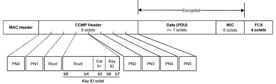
CCMP processing expands the original MPDU size by 16 octets, 8 octets for the CCMP Header field and 8 octets for the MIC field. The CCMP Header field is constructed from the PN, ExtIV, and Key ID subfields. PN is a 48-bit PN represented as an array of 6 octets. PN5 is the most significant octet of the PN, and PN0 is the least significant. Note that CCMP does not use the WEP ICV.
The ExtIV subfield (bit 5) of the Key ID octet signals that the CCMP Header field extends the MPDU header by a total of 8 octets, compared to the 4 octets added to the MPDU header when WEP is used. The ExtIV bit (bit5) is always set to 1 for CCMP.
Bits 6–7 of the Key ID octet are for the Key ID subfield.
The reserved bits shall be set to 0 and shall be ignored on reception.
CCMP cryptographic encapsulation
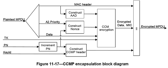
The CCMP cryptographic encapsulation process is depicted in Figure11-17.
CCMP encrypts the payload of a plaintext MPDU and encapsulates the resulting cipher text using the following steps:
a. Increment the PN, to obtain a fresh PN for each MPDU, so that the PN never repeats for the same temporal key. Note that retransmitted MPDUs are not modified on retransmission
b. Use the fields in the MPDU header to construct the additional authentication data (AAD) for CCM. The CCM algorithm provides integrity protection for the fields included in the AAD. MPDU header fields that may change when retransmitted are muted by being masked to 0 when calculating the AAD
c. Construct the CCM Nonce block from the PN, A2, and the Priority field of the MPDU where A2 is MPDU Address 2
d. Place the new PN and the key identifier into the 8-octet CCMP header
e. Use the temporal key, AAD, nonce, and MPDU data to form the cipher text and MIC. This step is known as CCM originator processing
f. Form the encrypted MPDU by combining the original MPDU header, the CCMP header, the encrypted data and MIC, as described in 11.4.3.2
The CCM reference describes the processing of the key, nonce, AAD, and data to produce the encrypted output See 11.4.3.3.2 to 11.4.3.3.6 for details of the creation of the AAD and nonce from the MPDU and the associated MPDU-specific processing.
PN processing
The PN is incremented by a positive number for each MPDU. The PN shall never repeat for a series of encrypted MPDUs using the same temporal key.
Construct AAD
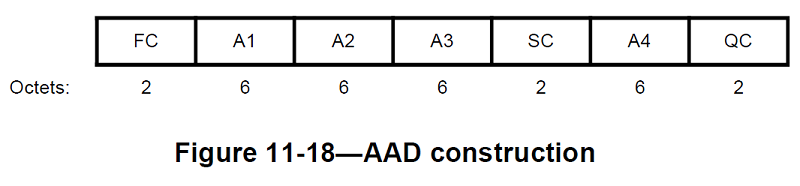
The format of the AAD is shown in Figure11-18
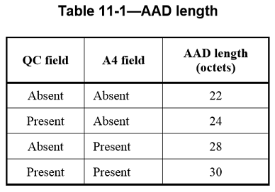
The length of the AAD varies depending on the presence or absence of the QC and A4 fields and is shown in Table11-1
The AAD is constructed from the MPDU header. The AAD does not include the header Duration field, because the Duration field value might change due to normal IEEE 802.11 operation (e.g., a rate change during retransmission). The AAD includes neither the Duration/ID field nor the HT Control field because the contents of these fields might change during normal operation (e.g., due to a rate change preceding retransmission). The HT Control field might also be inserted or removed during normal operation (e.g., retransmission of an A-MPDU where the original A-MPDU included an MRQ that has already generated a response). For similar reasons, several subfields in the Frame Control field are masked to 0. AAD construction is performed as follows:
a. FC – MPDU Frame Control field, with
- Subtype bits (bits 4 5 6) in a Data MPDU masked to 0
- Retry bit (bit 11) masked to 0
- Power Management bit (bit 12) masked to 0
- More Data bit (bit 13) masked to 0
- Protected Frame bit (bit 14) always set to 1
- Order bit (bit 15) as follows: i. Masked to 0 in all data MPDUs containing a QoS Control field ii. Unmasked otherwise
b. A1 – MPDU Address 1 field
c. A2 – MPDU Address 2 field
d. A3 – MPDU Address 3 field
e. SC – MPDU Sequence Control field, with the Sequence Number subfield (bits 4–15 of the Sequence Control field) masked to 0. The Fragment Number subfield is not modified
f. A4 – MPDU Address field, if present.
g. QC – QoS Control field, if present, a 2-octet field that includes the MSDU priority. The QC TID is used in the construction of the AAD. When both the STA and its peer have their SPP A-MSDU Capable fields equal to 1, bit 7 (the A-MSDU Present field) is used in the construction of the AAD. The remaining QC fields are masked to 0 for the AAD calculation (bits 4 to 6, bits 8 to 15, and bit 7 when either the STA or its peer has the SPP A-MSDU Capable field equal to 0).
Construct CCM nonce
The Nonce field occupies 13 octets, and its structure is shown in Figure11-19. The structure of the Nonce Flags subfield of the Nonce field is shown in Figure11-20
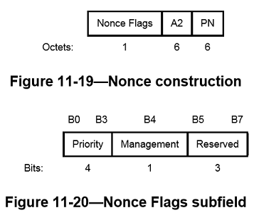
The Nonce field has an internal structure of Nonce Flags || A2 || PN (“||” is concatenation), where
- The Priority subfield of the Nonce Flags field shall be set to the fixed value 0 when there is no QC field present in the MPDU header. When the QC field is present, bits 0 to 3 of the Priority subfield shall be set to the value of the QC TID (bits 0 to 3 of the QC field)
- When management frame protection is negotiated, the Management field of the Nonce Flags field shall be set to 1 if the Type field of the Frame Control field is 00 (Management frame); otherwise it is set to 0
- Bits 5 to 7 of the Nonce Flags field are reserved and shall be set to 0 on transmission
- MPDU address A2 field occupies octets 1–6. This shall be encoded with the octets ordered with A2 octet0 at octet index 1 and A2 octet 5 at octet index 6
- The PN field occupies octets 7–12. The octets of PN shall be ordered so that PN0 is at octet index 12 and PN5 is at octet index 7.
Construct CCMP header
The format of the 8-octet CCMP header is given in 11.4.3.2. The header encodes the PN, Key ID, and ExtIV field values used to encrypt the MPDU.
CCM originator processing
CCM is a generic authenticate-and-encrypt block cipher mode, and in this standard, CCM is used with the AES block cipher. There are four inputs to CCM originator processing:
a. Key: the temporal key (16 octets)
b. Nonce: the nonce (13 octets) constructed as described in 11.4.3.3.4
c. Frame body: the frame body of the MPDU
d. AAD: the AAD (22–30 octets) constructed from the MPDU header as described in 11.4.3.3.3.
The CCM originator processing provides authentication and integrity of the frame body and the AAD as well as data confidentiality of the frame body. The output from the CCM originator processing consists of the encrypted data and 8 additional octets of encrypted MIC (see Figure11-16). A CCMP protected individually addressed robust management frame shall be protected with the TK.
CCMP decapsulation
CCMP decrypts the payload of a cipher text MPDU and decapsulates a plaintext MPDU using the following steps:
a. The encrypted MPDU is parsed to construct the AAD and nonce values
b. The AAD is formed from the MPDU header of the encrypted MPDU
c. The Nonce value is constructed from the A2, PN, and Nonce Flags fields
d. The MIC is extracted for use in the CCM integrity checking
e. The CCM recipient processing uses the temporal key, AAD, nonce, MIC, and MPDU cipher text data to recover the MPDU plaintext data as well as to check the integrity of the AAD and MPDU plaintext data
f. The received MPDU header and the MPDU plaintext data from the CCM recipient processing are concatenated to form a plaintext MPDU
g. The decryption processing prevents replay of MPDUs by validating that the PN in the MPDU is greater than the replay counter maintained for the session
When the received frame is a CCMP protected individually addressed robust management frame, contents of the MMPDU body after protection is removed shall be delivered to the SME via the MLME primitive designated for that management frame rather than through the MA-UNITDATA.indication primitive.
CCM recipient processing
CCM recipient processing uses the same parameters as CCM originator processing. A CCMP protected individually addressed robust management frame shall use the same TK as a Data MPDU.
Figure 11-21—CCMP decapsulation block diagram
There are four inputs to CCM recipient processing:
- Key: the temporal key (16 octets)
- Nonce: the nonce (13 octets) constructed as described in 11.4.3.3.4
- Encrypted frame body: the encrypted frame body from the received MPDU. The encrypted frame body includes an 8-octet MIC
- AAD: the AAD (22–30 octets) that is the canonical MPDU header as described in 11.4.3.3.3.
The CCM recipient processing checks the authentication and integrity of the frame body and the AAD as well as decrypting the frame body. The plaintext is returned only if the MIC check is successful. There is one output from error-free CCM recipient processing:
- Frame body: the plaintext frame body, which is 8 octets smaller than the encrypted frame body.
Decrypted CCMP MPDU
The decapsulation process succeeds when the calculated MIC matches the MIC value obtained from decrypting the received encrypted MPDU. The original MPDU header is concatenated with the plaintext data resulting from the successful CCM recipient processing to create the plaintext MPDU.
PN and replay detection
To effect replay detection, the receiver extracts the PN from the CCMP header. See 11.4.3.2 for a description of how the PN is encoded in the CCMP header. The following processing rules are used to detect replay:
a. The PN values sequentially number each MPDU
b. Each transmitter shall maintain a single PN (48-bit counter) for each PTKSA, GTKSA, and STKSA
c. The PN shall be implemented as a 48-bit monotonically incrementing non-negative integer, initialized to 1 when the corresponding temporal key is initialized or refreshed
d. A receiver shall maintain a separate set of PN replay counters for each PTKSA, GTKSA, and STKSA. The receiver initializes these replay counters to 0 when it resets the temporal key for a peer. The replay counter is set to the PN value of accepted CCMP MPDUs
e. For each PTKSA, GTKSA, and STKSA, the recipient shall maintain a separate replay counter for each IEEE 802.11 MSDU or A-MSDU priority and shall use the PN recovered from a received frame to detect replayed frames, subject to the limitation of the number of supported replay counters indicated in the RSN Capabilities field (see 8.4.2.27). A replayed frame occurs when the PN extracted from a received frame is less than or equal to the current replay counter value for the frame’s MSDU or A-MSDU priority and frame type. A transmitter shall not use IEEE 802.11 MSDU or A-MSDU priorities without ensuring that the receiver supports the required number of replay counters. The transmitter shall not reorder frames within a replay counter, but may reorder frames across replay counters. One possible reason for reordering frames is the IEEE 802.11 MSDU or A-MSDU priority
f. If dot11RSNAProtectedManagementFramesActivated is true, the recipient shall maintain a single replay counter for received individually addressed robust management frames and shall use the PN from the received frame to detect replays. A replayed frame occurs when the PN from the frame is less than or equal to the current management frame replay counter value. The transmitter shall preserve the order of protected robust management frames sent to the same DA
g. The receiver shall discard MSDUs, A-MSDUs, and MMPDUs whose constituent MPDU PN values are not sequential. A receiver shall discard any MPDU that is received with its PN less than or equal to the replay counter. When discarding a frame, the receiver shall increment by 1 the value of dot11RSNAStatsCCMPReplays for data frames or dot11RSNAStatsRobustMgmtCCMPReplays for robust management frames.
h. For MSDUs or A-MSDUs sent using the Block Ack feature, reordering of received MSDUs or AMSDUs according to the Block Ack receiver operation (described in 9.21.4) is performed prior to replay detection
Broadcast/multicast integrity protocol (BIP)
BIP provides data integrity and replay protection for group addressed robust Management frames after successful establishment of an IGTKSA (see 12.6.1.1.9). BIP-CMAC-128 provides data integrity and replay protection, using AES-128 in CMAC Mode with a 128-bit integrity key and a CMAC TLen value of 128 (16 octets). BIP-CMAC-256 provides data integrity and replay protection, using AES-256 in CMAC Mode with a 256-bit integrity key and a CMAC TLen value of 128 (16 octets). NIST Special Publication 800-38B defines the CMAC algorithm, and NIST SP 800-38D defines the GMAC algorithm. BIP processing uses AES with a 128-bit or 256-bit integrity key and a CMAC TLen value of 128 (16 octets). The CMAC output for BIP-CMAC-256 is not truncated and shall be 128 bits (16 octets). The CMAC output for BIP-CMAC-128 is truncated to 64 bits:
- MIC = Truncate-64(CMAC Output)
BIP-GCMP-128 uses AES with a 128-bit integrity key, and BIP-GCMP-256 uses AES with a 256-bit integrity key. The authentication tag for both BIP-GCMP-128 and BIP-GCMP-256 is not truncated and shall be 128 bits (16 octets)
BIP uses the IGTK to compute the MMPDU MIC. The authenticator shall distribute one new IGTK and IGTK PN (IPN) whenever it distributes a new GTK. The IGTK is identified by the MAC address of the transmitting STA plus an IGTK identifier that is encoded in the MME Key ID field
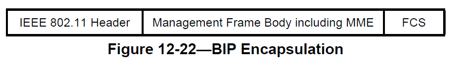
BIP MMPDU format
The Management MIC element shall follow all of the other elements in the management frame body but precede the FCS. See 9.4.2.55 for the format of the Management MIC element. Figure 12-22 shows the BIP MMPDU
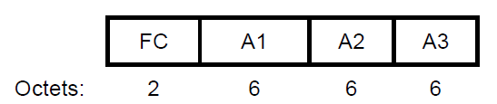
BIP AAD construction
The BIP Additional Authentication Data (AAD) shall be constructed from the MPDU header. The Duration field in the AAD shall be masked to 0. The AAD construction shall use a copy of the IEEE 802.11 header without the SC field for the MPDU, with the following exceptions:
a. FC—MPDU Frame Control field, with:
- Retry subfield (bit 11) masked to 0
- Power Management subfield (bit 12) masked to 0
- More Data subfield (bit 13) masked to 0
b. A1—MPDU Address 1 field
c. A2—MPDU Address 2 field
d. A3—MPDU Address 3 field
Figure 12-23 depicts the format of the AAD. The length of the AAD is 20 octets
BIP replay protection
The MME Sequence Number field represents a sequence number whose length is 6 octets. When management frame protection is negotiated, the receiver shall maintain a 48-bit replay counter for each IGTK. The receiver shall set the receive replay counter to the value of the IPN in the IGTK key data encapsulation (KDE) (see 12.7.2) provided by the Authenticator in either the 4-way handshake, FT 4-way handshake, FT handshake, or group key handshake. The transmitter shall maintain a single IPN for each IGTK. The IPN shall be implemented as a 48-bit strictly increasing integer, initialized to 1 when the corresponding IGTK is initialized. The transmitter may reinitialize the sequence counter when the IGTK is refreshed. See 12.5.4.5 and 12.5.4.6 for per packet BIP processing.
NOTE—When the IPN space is exhausted, the choices available to an implementation are to replace the IGTK or to end communications
When dot11QMFActivated is true, the receiver shall maintain an additional replay counter for each ACI for received group addressed robust Management frames that use QMF. The receiver shall use the ACI encoded in the Sequence Number field of received GQMFs protected by BIP to select the replay counter to use for the received frame, and shall use the IPN from the received frame to detect replays
If dot11RSNAProtectedManagementFramesActivated is true and dot11MeshSecurityActivated is true, the recipient shall maintain a single replay counter for received group addressed robust Management frames that do not use the QMF service and shall use the PN from the received frame to detect replays. If dot11QMFActivated is also true, the recipient shall maintain an additional replay counter for each ACI for received group addressed robust Management frames that use the QMF service. The QMF receiver shall use the ACI encoded in the Sequence Number field of the received frame to select the replay counter to use for the received frame, and shall use the PN from the received frame to detect replays. A replayed frame occurs when the PN from the frame is less than or equal to the value of the management frame replay counter that corresponds to the ACI of the frame. The transmitter shall preserve the order of protected robust Management frames transmitted to the same DA without the QMF service. When the QMF service is used, the transmitter shall not reorder robust GQMFs within an AC when the frames are transmitted to the same RA
BIP transmission
When a STA transmits a protected group addressed robust Management frame, it shall
a. Select the IGTK currently active for transmission of frames to the intended group of recipients and construct the MME (see 9.4.2.55) with the MIC field masked to 0 and the Key ID field set to the corresponding IGTK Key ID value. If the frame is not a GQMF, the transmitting STA shall insert a strictly increasing integer into the MME IPN field. If the frame is a GQMF, then the transmitting STA shall maintain a 48-bit counter for use as the IPN, the counter shall be incremented for each GQMF until the two least significant bits of the counter match the ACI of the AC that is used to transmit the frame, and the counter value shall be inserted into the MME IPN field of the frame. For BIP-GMAC-128 and BIP-GMAC-256, the initialization vector passed to GMAC shall be a concatenation of Address 2 from the MAC header of the MPDU and the non-negative integer inserted into the MMP IPN field
b. Compute AAD as specified in 12.5.4.3
c. Compute an integrity value over the concatenation of AAD and the management frame body including MME, and insert the output into the MME MIC field. For BIP-CMAC-128, the integrity value is 64 bits and is computed using AES-128-CMAC; for BIP-CMAC-256, the integrity value is 128 bits and is computed using AES-256-CMAC; for BIP-GMAC-128, the integrity value is 128 bits and is computed using AES-128-GMAC; and, for BIP-GMAC-256, the integrity value is 128 bits and is computed using AES-256-GMAC.
d. Compose the frame as the IEEE 802.11 header, management frame body, including MME, and FCS. The MME shall appear last in the frame body
e. Transmit the frame
BIP reception
When a STA with management frame protection negotiated receives a group addressed robust Management frame protected by BIP-CMAC-128, BIP-CMAC-256, BIP-GMAC-128, or BIP-GMAC-256, it shall
a. Identify the appropriate IGTK and associated state based on the MME Key ID field. If no such IGTK exists, silently drop the frame and terminate BIP processing for this reception
b. Perform replay protection on the received frame. The receiver shall interpret the MME IPN field as a 48-bit unsigned integer
- If the frame is not a GQMF, the receiver shall compare this MME IPN integer value to the value of the receive replay counter for the IGTK identified by the MME Key ID field. If the integer value from the received MME IPN field is less than or equal to the replay counter value for this IGTK, the receiver shall discard the frame and increment the dot11RSNAStatsCMACReplays counter by 1
- If the frame is a GQMF, the receiver shall compare this MME IPN integer value to the value of the receive replay counter for the IGTK identified by the MME Key ID field and the AC represented by the value of the ACI subfield of the received frame. If the integer value from the received MME IPN field is less than or equal to the replay counter value for this IGTK and AC, the receiver shall discard the frame and increment the dot11RSNAStatsCMACReplays counter by 1
c. Compute AAD for this Management frame, as specified in 12.5.4.3. For BIP-GMAC-128 and BIPGMAC-256, an initialization vector for GMAC is constructed as the concatenation of Address 2 from the MAC header of the MPDU and the 48-bit unsigned integer from the MME IPN field
d. Extract and save the received MIC value, and compute a verifier over the concatenation of AAD, the management frame body, and MME, with the MIC field masked to 0 in the MME. For BIP-CMAC-128, the integrity value is 64 bits and is computed using AES-128-CMAC; for BIP-CMAC-256, the integrity value is 128 bits and is computed using AES-256-CMAC; for BIP-GMAC-128, the integrity value is 128 bits and is computed using AES-128-GMAC; and, for BIP-GMAC-256, the integrity value is 128 bits and is computed using AES-256-GMAC. If the result does not match the received MIC value, then the receiver shall discard the frame, increment the dot11RSNAStatsBIPMICErrors counter by 1, and terminate BIP processing for this reception
e. If the frame is not a GQMF, update the replay counter for the IGTK identified by the MME Key ID field with the integer value of the MME IPN field
f. If the frame is a GQMF, update the replay counter for the IGTK identified by the MME Key ID field and the AC represented by the value of the ACI subfield of the received frame with the integer value of the MME IPN field
If management frame protection is negotiated, group addressed robust Management frames that are received without BIP protection shall be discarded
AES-GCM Use in Wifi
IEEE-802.11-2016 specifies the GCMP, which provides data confidentiality, authentication, integrity, and replay protection. A DMG RSNA STA shall support GCMP-128. GCMP is based on the GCM of the AES encryption algorithm. GCM protects the integrity of both the MPDU Data field and selected portions of the MPDU header. The AES algorithm is defined in FIPS PUB 197. All AES processing used within GCMP uses AES with a 128-bit key (GCMP-128) or a 256-bit key (GCMP-256). GCM is defined in NIST Special Publication 800-38D. GCM is a generic mode that can be used with any block-oriented encryption algorithm
GCM requires a fresh temporal key for every session. GCM also requires a unique nonce value for each frame protected by a given temporal key, and GCMP uses a 96-bit nonce that includes a 48-bit packet number (PN) for this purpose. Reuse of a PN with the same temporal key voids all security guarantees. GCMP uses a 128-bit MIC
When GCMP is selected as the RSN pairwise cipher and management frame protection is negotiated, individually addressed robust Management frames and the group addressed Management frames that receive “Group Addressed Privacy” as indicated in Table 9-47 shall be protected with GCMP
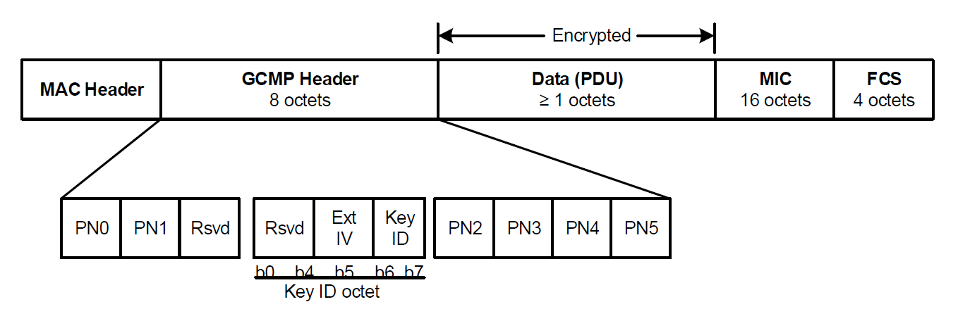
GCMP MPDU format
Figure12-24 depicts the MPDU when using GCMP
GCMP cryptographic encapsulation
GCMP encrypts the Frame Body field of a plaintext MPDU and encapsulates the resulting cipher text using the following steps:
a. Increment the PN, to obtain a fresh PN for each MPDU, so that the PN never repeats for the same temporal key
b. Use the fields in the MPDU header to construct the additional authentication data (AAD) for GCM. The GCM algorithm provides integrity protection for the fields included in the AAD. MPDU header fields that may change when retransmitted are masked to 0 when calculating the AAD
c. Construct the GCM Nonce block from the PN and A2, where A2 is MPDU Address 2
d. Place the new PN and the key identifier into the 8-octet GCMP Header
e. Use the temporal key, AAD, nonce, and MPDU data to form the cipher text and MIC. This step is known as GCM originator processing
f. Form the encrypted MPDU by combining the original MPDU header, the GCMP header, the encrypted data and MIC
GCMP PN processing
The PN is incremented by a positive number for each MPDU. The PN shall be incremented in steps of 1 for constituent MPDUs of fragmented MSDUs and MMPDUs. The PN shall never repeat for a series of encrypted MPDUs using the same temporal key. If the PN is larger than dot11PNExhaustionThreshold, an MLME-PN-EXHAUSTION.indication primitive shall be generated
Construct AAD
The AAD for GCMP is constructed in the same manner as CCMP
Construct GCM nonce
The Nonce field occupies 12 octets, and its structure is shown in Figure 12-26

The Nonce field has an internal structure of A2 || PN, where
- MPDU address A2 field occupies octets 0 to 5. This shall be encoded with the octets ordered with A2 octet 0 at octet index 0 and A2 octet 5 at octet index 5
- The PN field occupies octets 6 to 11. The octets of PN shall be ordered so that PN0 is at octet index 11 and PN5 is at octet index 6
GCM originator processing
GCM is a generic authenticate-and-encrypt block cipher mode, and in this standard, GCM is used with the AES block cipher
There are four inputs to GCM originator processing:
a. Key: the temporal key (16 octets)
b. Nonce: the nonce (12 octets) constructed as described in 12.5.5.3.4
c. Frame body: the plaintext frame body of the MPDU
d. AAD: the AAD (22-30 octets) constructed from the MPDU header as described in 12.5.5.3.3
The GCM originator processing provides authentication and integrity of the frame body and the AAD as well as data confidentiality of the frame body. The output from the GCM originator processing consists of the encrypted data and 16 additional octets of encrypted MIC (see Figure 12-24). The PN values sequentially number each MPDU. Each transmitter shall maintain a single PN (48-bit counter) for each PTKSA, GTKSA, and STKSA. The PN shall be implemented as a 48-bit strictly increasing integer, initialized to 1 when the corresponding temporal key is initialized or refreshed
A transmitter shall not use IEEE 802.11 MSDU or A-MSDU priorities without ensuring that the receiver supports the required number of replay counters. The transmitter shall not reorder GCMP protected frames that are transmitted to the same RA within a replay counter, but may reorder frames across replay counters
One possible reason for reordering frames is the IEEE 802.11 MSDU or A-MSDU priority. The transmitter shall preserve the order of protected robust Management frames that are transmitted to the same DA without the QMF service. When the QMF service is used, the transmitter shall not reorder robust IQMFs within an AC when the frames are transmitted to the same RA
A GCMP protected individually addressed robust Management frame shall be protected using the same TK as a Data frame
GCMP decapsulation
GCMP decrypts the Frame Body field of a cipher text MPDU and decapsulates a plaintext MPDU using the following steps:
a. The encrypted MPDU is parsed to construct the AAD and nonce values
b. The AAD is formed from the MPDU header of the encrypted MPDU
c. The Nonce value is constructed from the A2 and PN fields
d. The MIC is extracted for use in the GCM integrity checking
e. The GCM recipient processing uses the temporal key, AAD, nonce, MIC, and MPDU cipher text data to recover the MPDU plaintext data as well as to check the integrity of the AAD and MPDU plaintext data
f. The received MPDU header and the MPDU plaintext data from the GCM recipient processing are concatenated to form a plaintext MPDU
g. The decryption processing prevents replay of MPDUs by validating that the PN in the MPDU is greater than the replay counter maintained for the session
When the received frame is a GCMP protected individually addressed robust Management frame, the contents of the MMPDU body after protection is removed and shall be delivered to the SME via the MLME primitive designated for that MMPDU rather than through the MA-UNITDATA.indication primitive
GCM recipient processing
GCM recipient processing shall use the same parameters as GCM originator processing. A GCMP protected individually addressed robust Management frame shall use the same TK as a Data frame
There are four inputs to GCM recipient processing:
- Key: the temporal key (16 octets)
- Nonce: the nonce (12 octets) constructed as described in 12.5.5.3.4
- Encrypted frame body: the encrypted frame body from the received MPDU. The encrypted frame body includes a 16-octet MIC
- AAD: the AAD (22-30 octets) that is the canonical MPDU header as described in 12.5.5.3.3
The GCM recipient processing checks the authentication and integrity of the frame body and the AAD as well as decrypting the frame body. The plaintext is returned only if the MIC check is successful
There is one output from error-free GCM recipient processing:
- Frame body: the plaintext frame body, which is 16 octets smaller than the encrypted frame body
Decrypted GCMP MPDU
The decapsulation process succeeds when the calculated MIC matches the MIC value obtained from decrypting the received encrypted MPDU. The original MPDU header is concatenated with the plaintext data resulting from the successful GCM recipient processing to create the plaintext MPDU
PN and replay detection
To effect replay detection, the receiver extracts the PN from the GCMP header. See 12.5.5.2 for a description of how the PN is encoded in the GCMP header. The following processing rules are used to detect replay:
a. The receiver shall maintain a separate set of replay counters for each PTKSA, GTKSA, and STKSA. The receiver initializes these replay counters to 0 when it resets the temporal key for a peer. The replay counter is set to the PN value of accepted GCMP MPDUs
b. For each PTKSA, GTKSA, and STKSA, the recipient shall maintain a separate replay counter for each TID, subject to the limitation of the number of supported replay counters indicated in the RSN Capabilities field (see 9.4.2.25), and shall use the PN from a received frame to detect replayed frames. A replayed frame occurs when the PN from a received frame is less than or equal to the current replay counter value for the frame’s MSDU or A-MSDU priority and frame type
c. If dot11RSNAProtectedManagementFramesActivated is true, the recipient shall maintain a single replay counter for received individually addressed robust Management frames that are received with the To DS subfield equal to 0 and shall use the PN from the received frame to detect replays. If dot11QMFActivated is also true, the recipient shall maintain an additional replay counter for each ACI for received individually addressed robust Management frames that are received with the To DS subfield equal to 1. The QMF receiver shall use the ACI encoded in the Sequence Number field of the received frame to select the replay counter to use for the received frame, and shall use the PN from the received frame to detect replays. A replayed frame occurs when the PN from the frame is less than or equal to the current value of the management frame replay counter that corresponds to the ACI of the frame
d. The receiver shall discard any Data frame that is received with its PN less than or equal to the value of the replay counter that is associated with the TA and priority value of the received MPDU. The receiver shall discard MSDUs and MMPDUs whose constituent MPDU PN values are not incrementing in steps of 1. If dot11RSNAProtectedManagementFramesActivated is true, the receiver shall discard any individually addressed robust Management frame that is received with its PN less than or equal to the value of the replay counter associated with the TA of that individually addressed Management frame
e. When discarding a frame, the receiver shall increment by 1 dot11RSNAStatsGCMPReplays for Data frames or dot11RSNAStatsRobustMgmtGCMPReplays for robust Management frames
f. For MSDUs or A-MSDUs sent using the block ack feature, reordering of received MSDUs or A-MSDUs according to the block ack receiver operation (described in 10.24.4) is performed prior to replay detection
MAC frame formats
Each frame consists of the following basic components:
a. A MAC header, which comprises frame control, duration, address, optional sequence control information, optional QoS Control information (QoS data frames only), and optional HT Control fields (+HTC frames only)
b. A variable-length frame body, which contains information specific to the frame type and subtype
c. A FCS, which contains an IEEE 32-bit CRC
Conventions
Structures defined in the MAC sublayer are described as a sequence of fields in specific order. Each figure in Clause 8 depicts the fields/subfields as they appear in the MAC frame and in the order in which they are passed to the physical layer convergence procedure (PLCP), from left to right.
In figures, all bits within fields are numbered, from 0 to k, where the length of the field is k + 1 bits. Bits within numeric fields that are longer than a single bit are depicted in increasing order of significance, i.e., with the lowest numbered bit having the least significance. The octet boundaries within a field can be obtained by taking the bit numbers of the field modulo 8. Octets within numeric fields that are longer than a single octet are depicted in increasing order of significance, from lowest numbered bit to highest numbered bit. The octets in fields longer than a single octet are sent to the PLCP in order from the octet containing the lowest numbered bits to the octet containing the highest numbered bits.
Any field containing a CRC is an exception to this convention and is transmitted commencing with the coefficient of the highest-order term.
MAC addresses are assigned as ordered sequences of bits. The Individual/Group bit is always transferred first and is bit 0 of the first octet.
Organizationally unique identifiers (OUIs) and Organization Identifiers are specified in two forms: an ordered sequence of octets, and a numeric form. Treating the OUI or Organization Identifier as an ordered sequence of octets, the leftmost octet is always transferred first. This is equivalent to transmitting the most significant octet of the numeric form first.
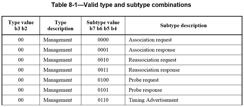
Values specified in decimal are coded in natural binary unless otherwise stated. The values in Table8-1 are in binary, with the bit assignments shown in the table. Values in other tables are shown in decimal notation.
Reception, in references to frames or fields within frames (e.g., received Beacon frames or a received Duration/ID field), applies to MPDUs or MAC management protocol data units (MMPDUs) indicated from the PHY layer without error and validated by FCS within the MAC sublayer. Without further qualification, reception by the MAC sublayer implies that the frame contents are valid, and that the protocol version is supported (see 8.2.4.1.2), with no implication regarding frame addressing or regarding whether the frame type or other fields in the MAC header are meaningful to the MAC entity that has received the frame.
A frame that contains the HT Control field, including the Control Wrapper frame, is referred to as a +HTC frame. A QoS Data frame that is transmitted by a mesh STA is referred to as a Mesh Data frame.
Parentheses enclosing portions of names or acronyms are used to designate a set of related names that vary based on the inclusion of the parenthesized portion. For example,
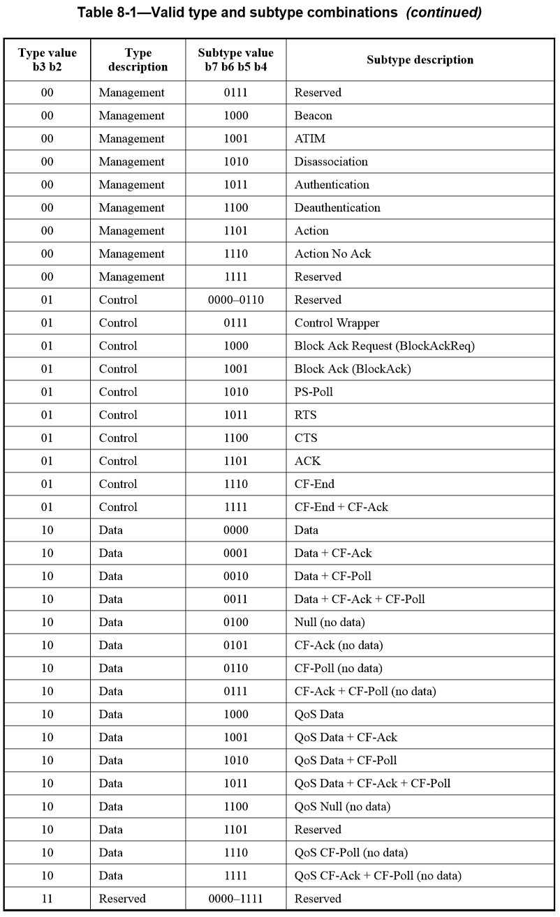
- QoS +CF-Poll frame refers to the three QoS data subtypes that include “+CF-Poll”: the QoS Data+CF-Poll frame, subtype 1010; QoS Data+CF-Ack+CF-Poll frame, subtype 1011; and QoS CFAck+CF-Poll frame, subtype 1111
- QoS CF-Poll frame refers specifically to the QoS CF-Poll frame, subtype 1110
- QoS (+)CF-Poll frame refers to all four QoS data subtypes with CF-Poll: the QoS CF-Poll frame, subtype 1110; the QoS CF-Ack+CF-Poll frame, subtype 1111; the QoS Data+CF-Poll frame, subtype 1010; and the QoS Data+CF-Ack+CF-Poll frame, subtype 1011
- QoS (+)Null frame refers to all three QoS data subtypes with “no data”: the QoS Null (no data) frame, subtype 1100; the QoS CF-Poll (no data) frame, subtype 1110; and the QoS CF-Ack+CF-Poll frame, subtype 1111
- QoS +CF-Ack frame refers to the three QoS data subtypes that include “+CF-Ack”: the QoS Data+CF-Ack frame, subtype 1001; QoS Data+CF-Ack+CF-Poll frame, subtype 1011; and QoS CF-Ack+CF-Poll frame, subtype 1111
- Whereas (QoS) CF-Poll frame refers to the QoS CF-Poll frame, subtype 1110, and the CF-Poll frame, subtype 0110.
Reserved fields and subfields are set to 0 upon transmission and are ignored upon reception.
General frame format
The MAC frame format comprises a set of fields that occur in a fixed order in all frames. Figure8-1 depicts the general MAC frame format. The first three fields (Frame Control, Duration/ID, and Address 1) and the last field (FCS) in Figure8-1 constitute the minimal frame format and are present in all frames, including reserved types and subtypes. The fields Address 2, Address 3, Sequence Control, Address 4, QoS Control, HT Control, and Frame Body are present only in certain frame types and subtypes. Each field is defined in 8.2.4. The format of each of the individual subtypes of each frame type is defined in 8.3. The components of management frame bodies are defined in 8.4. The formats of management frames of subtype Action are defined in 8.5.
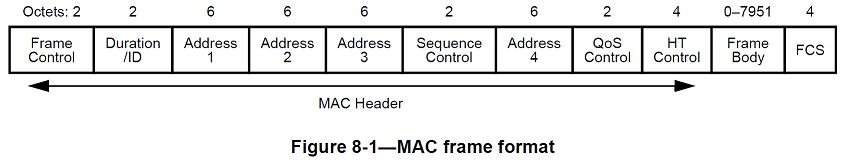
The Frame Body field is of variable size. The maximum frame body size is determined by the maximum MSDU size (2304 octets), plus the length of the Mesh Control field (6, 12, or 18 octets) if present, the maximum unencrypted MMPDU size excluding the MAC header and FCS (2304 octets) or the maximum AMSDU size (3839 or 7935 octets, depending upon the STA’s capability), plus any overhead from security encapsulation.
Frame fields
The Frame Control field consists of the following subfields: Protocol Version, Type, Subtype, To DS, FromDS, More Fragments, Retry, Power Management, More Data, Protected Frame, and Order. The format of the Frame Control field is illustrated in Figure8-2.
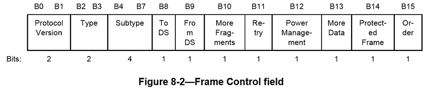
Protocol Version field
The Protocol Version field is 2 bits in length and is invariant in size and placement across all revisions of this standard. For this standard, the value of the protocol version is 0. All other values are reserved. The revision level will be incremented only when a fundamental incompatibility exists between a new revision and the prior edition of the standard. See 9.24.2.
Type and Subtype fields
The Type field is 2 bits in length, and the Subtype field is 4 bits in length. The Type and Subtype fields together identify the function of the frame. There are three frame types: control, data, and management. Each of the frame types has several defined subtypes. In data frames, the most significant bit (MSB) of the Subtype field, b7, is defined as the QoS subfield. Table8-1 defines the valid combinations of type and subtype. (The numeric values in Table8-1 are shown in binary, see IEEE802.11-2012)
Each Subtype field bit position is used to indicate a specific modification of the basic data frame (subtype 0). Frame Control bit 4 is set to 1 in data subtypes that include +CF-Ack, bit 5 is set to 1 in data subtypes that include +CF-Poll, bit 6 is set to 1 in data subtypes that contain no Frame Body field, and bit 7 is set to 1 in the QoS data subtypes, which have QoS Control fields in their MAC headers.
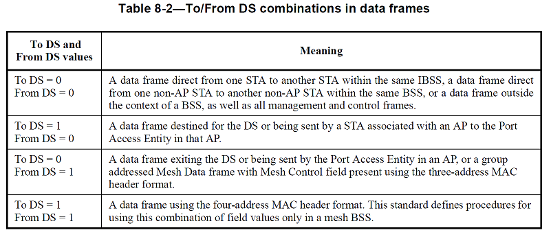
To DS and From DS fields
The meaning of the combinations of values for the To DS and From DS fields are shown in Table8-2
More Fragments field
The More Fragments field is 1 bit in length and is set to 1 in all data or management type frames that have another fragment of the current MSDU or current MMPDU to follow. It is set to 0 in all other frames.
Retry field
The Retry field is 1 bit in length and is set to 1 in any data or management type frame that is a retransmission of an earlier frame. It is set to 0 in all other frames. A receiving STA uses this indication to aid in the process of eliminating duplicate frames.
Power Management field
The Power Management field is 1 bit in length and is used to indicate the power management mode of a STA. The value of this field is either reserved (as defined below) or remains constant in each frame from a particular STA within a frame exchange sequence (see AnnexG). The value indicates the mode of the STA after the successful completion of the frame exchange sequence.
In an infrastructure BSS, the following applies:
- The Power Management field is reserved in all management frames that are not bufferable management frames
- The Power Management field is reserved in all management frames transmitted by a STA to an AP with which it is not associated
- The Power Management field is reserved in all frames transmitted by the AP
- Otherwise, a value of 1 indicates that the STA will be in PS mode. A value of 0 indicates that the STA will be in active mode.
In an IBSS, the following applies:
- The Power Management field is reserved in all management frames that are not bufferable management frames and that are not individually addressed Probe Request frames
- Otherwise, a value of 1 indicates that the STA will be in PS mode. A value of 0 indicates that the STA will be in active mode.
In an MBSS, the following applies:
- A value of 0 in group addressed frames, in management frames transmitted to nonpeer STAs, and in Probe Response frames indicates that the mesh STA will be in active mode towards all neighbor mesh STAs. A value of 1 in group addressed frames, in management frames transmitted to nonpeer STAs, and in Probe Response frames indicates that the mesh STA will be in deep sleep mode towards all nonpeer mesh power STAs
- A value of 0 in individually addressed frames transmitted to a peer mesh STA indicates that the mesh STA will be in active mode towards this peer mesh STA A value of 1 in individually addressed frames transmitted to a peer mesh STA, except Probe Response frames, indicates that the mesh STA will be in either light sleep mode or deep sleep mode towards this peer mesh STA. When the QoS Control field is present in the frame, the Mesh Power Save Level subfield in the QoS Control field indicates whether the mesh STA will be in light sleep mode or in deep sleep mode for the recipient mesh STA as specified in 8.2.4.5.11.
The mesh power mode transition rules are described in 13.14.3.
More Data field
The More Data field is 1 bit in length and is used to indicate to a STA in PS mode that more BUs are buffered for that STA at the AP. The More Data field is valid in individually addressed data or management type frames transmitted by an AP to a STA in PS mode. A value of 1 indicates that at least one additional buffered BU is present for the same STA.
The More Data field is optionally set to 1 in individually addressed data type frames transmitted by a CF Pollable STA to the PC in response to a CF-Poll to indicate that the STA has at least one additional buffered MSDU available for transmission in response to a subsequent CF-Poll.
For a STA in which the More Data Ack subfield of its QoS Capability element is 1 and that has APSD enabled, an AP optionally sets the More Data field to 1 in ACK frames to this STA to indicate that the AP has a pending transmission for the STA.
For a STA with TDLS peer PSM enabled and the More Data Ack subfield equal to 1 in the QoS Capability element of its transmitted TDLS Setup Request frame or TDLS Setup Response frame, a TDLS peer STA optionally sets the More Data field to 1 in ACK frames to this STA to indicate that it has a pending transmission for the STA.
The More Data field is 1 in individually addressed frames transmitted by a mesh STA to a peer mesh STA that is either in light sleep mode or in deep sleep mode for the corresponding mesh peering, when additional BUs remain to be transmitted to this peer mesh STA.
The More Data field is set to 0 in all other individually addressed frames.
The More Data field is set to 1 in group addressed frames transmitted by the AP when additional group addressed bufferable units (BUs) remain to be transmitted by the AP during this beacon interval. The More Data field is set to 0 in group addressed frames transmitted by the AP when no more group addressed BUs remain to be transmitted by the AP during this beacon interval and in all group addressed frames transmitted by non-AP STAs.
The More Data field is 1 in group addressed frames transmitted by a mesh STA when additional group addressed BUs remain to be transmitted. The More Data field is 0 in group addressed frames transmitted by a mesh STA when no more group addressed BUs remain to be transmitted.
Protected Frame field
The Protected Frame field is 1 bit in length. The Protected Frame field is set to 1 if the Frame Body field contains information that has been processed by a cryptographic encapsulation algorithm. The Protected Frame field is set to 1 only within data frames and within management frames of subtype Authentication, and individually addressed robust management frames. The Protected Frame field is set to 0 in all other frames. When the Protected Frame field is equal to 1, the Frame Body field is protected utilizing the cryptographic encapsulation algorithm and expanded as defined in Clause 11. The Protected Frame field is set to 0 in Data frames of subtype Null Function, CF-ACK (no data), CF-Poll (no data), CF-ACK+CF-Poll (no data), QoS Null (no data), QoS CF-Poll (no data), and QoS CF-ACK+CF-Poll (no data) (see, for example, 11.4.2.2 and 11.4.3.1 that show that the frame body needs to be 1 octet or longer to apply the encapsulation).
Order field
The Order field is 1 bit in length. It is used for two purposes:
- It is set to 1 in a non-QoS data frame transmitted by a non-QoS STA to indicate that the frame contains an MSDU, or fragment thereof, that is being transferred using the StrictlyOrdered service class
- It is set to 1 in a QoS data or management frame transmitted with a value of HT_GF or HT_MF for the FORMAT parameter of the TXVECTOR to indicate that the frame contains an HT Control field. Otherwise, the Order field is set to 0.
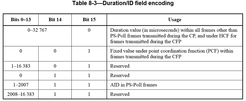
Duration/ID field
The Duration/ID field is 16 bits in length. The contents of this field vary with frame type and subtype, with whether the frame is transmitted during the CFP, and with the QoS capabilities of the sending STA. The contents of the field are defined as follows:
a. In control frames of subtype PS-Poll, the Duration/ID field carries the association identifier (AID) of the STA that transmitted the frame in the 14 least significant bits (LSB), and the 2 most significant bits (MSB) both set to 1. The value of the AID is in the range 1–2007
b. In frames transmitted by the PC and non-QoS STAs, during the CFP, the Duration/ID field is set to a fixed value of 32768
c. In all other frames sent by non-QoS STAs and control frames sent by QoS STAs, the Duration/ID field contains a duration value as defined for each frame type in 8.3
d. In data and management frames sent by QoS STAs, the Duration/ID field contains a duration value as defined for each frame type in 8.2.5.
See 9.24.3 on the processing of this field in received frames.
The encoding of the Duration/ID field is given in Table8-3.
The Duration/ID fields in the MAC headers of MPDUs in an A-MPDU all carry the same value NOTE—The reference point for the Duration/ID field is the end of the PPDU carrying the MPDU Setting the Duration/ ID field to the same value in the case of A-MPDU aggregation means that each MPDU consistently specifies the same NAV setting.
Address fields
There are four address fields in the MAC frame format. These fields are used to indicate the basic service set identifier (BSSID), source address (SA), destination address (DA), transmitting STA address (TA), and receiving STA address (RA). Certain frames may not contain some of the address fields.
Certain address field usage is specified by the relative position of the address field (1–4) within the MAC header, independent of the type of address present in that field. For example, receiver address matching is always performed on the contents of the Address 1 field in received frames, and the receiver address of CTS and ACK frames is always obtained from the Address 2 field in the corresponding RTS frame, or from the frame being acknowledged.
Address representation
Each Address field contains a 48-bit address as defined in 9.2 of IEEE Std 802-2001
Address designation
A MAC sublayer address is one of the following two types:
a. Individual address. The address assigned to a particular STA on the network
b. Group address. A multidestination address, which may be in use by one or more STAs on a given network. The two kinds of group addresses are as follows:
- Multicast-group address. An address associated by higher level convention with a group of logically related STAs
- Broadcast address. A distinguished, predefined group address that always denotes the set of all STAs on a given LAN. All ones are interpreted to be the broadcast address. This group is predefined for each communication medium to consist of all STAs actively connected to that medium; it is used to broadcast to all the active STAs on that medium.
The address space is also partitioned into locally administered and universal (globally administered) addresses. The nature of a body and the procedures by which it administers these universal (globally administered) addresses is beyond the scope of this standard. See IEEE Std 802-2001 for more information
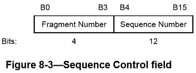
Sequence Control field
The Sequence Control field is 16 bits in length and consists of two subfields, the Sequence Number and the Fragment Number. The format of the Sequence Control field is illustrated in Figure8-3. The sequence Control field is not present in control frames.
Sequence Number field
The Sequence Number field is a 12-bit field indicating the sequence number of an MSDU, A-MSDU, or MMPDU. Each MSDU, A-MSDU, or MMPDU transmitted by a STA is assigned a sequence number. Sequence numbers are not assigned to control frames, as the Sequence Control field is not present.
Each fragment of an MSDU or MMPDU contains a copy of the sequence number assigned to that MSDU or MMPDU. The sequence number remains constant in all retransmissions of an MSDU, MMPDU, or fragment thereof.
Fragment Number field
The Fragment Number field is a 4-bit field indicating the number of each fragment of an MSDU or MMPDU. The fragment number is set to 0 in the first or only fragment of an MSDU or MMPDU and is incremented by one for each successive fragment of that MSDU or MMPDU. The fragment number is set to 0 in the only fragment of an A-MSDU. The fragment number remains constant in all retransmissions of the fragment.
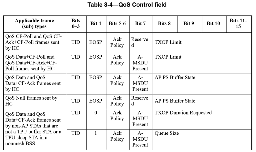
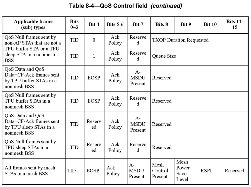
QoS Control field
The QoS Control field is a 16-bit field that identifies the TC or TS to which the frame belongs as well as various other QoS-related, A-MSDU related, and mesh-related information about the frame that varies by frame type, subtype, and type of transmitting STA. The QoS Control field is present in all data frames in which the QoS subfield of the Subtype field is equal to 1 (see 8.2.4.1.3). Each QoS Control field comprises five or eight subfields, as defined for the particular sender (HC or non-AP STA) and frame type and subtype. The usage of these subfields and the various possible layouts of the QoS Control field are described 8.2.4.5.2 to 8.2.4.5.12 and illustrated in Table8-4 of the IEEE802.11-2012 specification
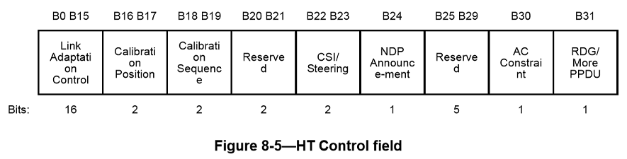
HT Control field
The HT Control field is always present in a Control Wrapper frame and is present in QoS Data and management frames as determined by the Order bit of the Frame Control field as defined in 8.2.4.1.10. NOTE—The only Control frame subtype for which HT Control field is present is the Control Wrapper frame. A control frame that is described as +HTC (e.g., RTS+HTC, CTS+HTC, BlockAck+HTC or BlockAckReq+HTC) implies the use of the Control Wrapper frame to carry that control frame. The format of the 4-octet HT Control field is shown in Figure8-5. Subfields of the HT control field are defined in the 8.2.4.6 section of the IEEE802.11-2012 specification.
Frame Body field
The Frame Body is a variable-length field that contains information specific to individual frame types and subtypes. The minimum length of the frame body is 0 octets. The maximum length of the frame body is defined by the maximum length MSDU plus the length of Mesh Control field as defined in 8.2.4.7.3, if present, plus any overhead for encryption as defined in Clause11, or by the maximum length A-MSDU plus any overhead for encryption as defined in Clause11.
Overhead for encryption
The overhead for encryption is described in Clause11. When the Mesh Control field is present in the frame body, the Mesh Control field is encrypted as a part of data.
Mesh Control field
The Mesh Control field is present in the unfragmented Mesh Data frame, in the first fragment of the Mesh Data frame, and in the management frame of subtype Action, Category Multihop Action (Multihop Action frame) transmitted by a mesh STA.
In Mesh Data frames, when the Mesh Control Present subfield in the QoS Control field is 1, the Mesh Control field is prepended to the MSDU and located as follows:
- When the frame body contains an MSDU (or a fragment thereof) and the frame is not encrypted, the Mesh Control field is located in the first octets of the frame body
- When the frame body contains an MSDU (or a fragment thereof) and the frame is encrypted, the Mesh Control field is located in the first octets of the encrypted data portion
- When the frame body contains an A-MSDU, the Mesh Control field is located in the Aggregate MSDU subframe header as shown in Figure8-33.
In the Multihop Action frame, the Mesh Control field is present as specified in 8.5.18.
The Mesh Control field is of variable length (6, 12, or 18 octets). The structure of the Mesh Control field is defined in Figure8-9.
FCS field
The FCS field is a 32-bit field containing a 32-bit CRC. The FCS is calculated over all the fields of the MAC header and the Frame Body field. These are referred to as the calculation fields.
The FCS is calculated using the following standard generator polynomial of degree 32:
![\[ G(x) = {x}^{32} + {x}^{26} + {x}^{23} + {x}^{22} + {x}^{16} + {x}^{12} + {x}^{11} + {x}^{10} + x^8 + x^7 + x^5 + x^4 + x^2 + x + 1 \]](form_445.png)
The FCS is the ones complement of the sum (modulo 2) of the following:
a. The remainder of  divided (modulo 2) by G(x), where k is the number of bits in the calculation fields, and
b. The remainder after multiplication of the contents (treated as a polynomial) of the calculation fields by  and then division by G(x).
The FCS field is transmitted commencing with the coefficient of the highest-order term.
As a typical implementation, at the transmitter, the initial remainder of the division is preset to all ones and is then modified by division of the calculation fields by the generator polynomial G(x). The ones complement of this remainder is transmitted, with the highest-order bit first, as the FCS field.
At the receiver, the initial remainder is preset to all ones and the serial incoming bits of the calculation fields and FCS, when divided by G(x), results (in the absence of transmission errors) in a unique nonzero remainder value. The unique remainder value is the polynomial:
![\[ G(x) = {x}^{31} + {x}^{30} + {x}^{26} + {x}^{25} + {x}^{24} + {x}^{18} + {x}^{15} + {x}^{14} + {x}^{12} + {x}^{11} + {x}^{10} + x^8 + x^6 + x^5 + x^4 + x^3 + x + 1 \]](form_448.png)
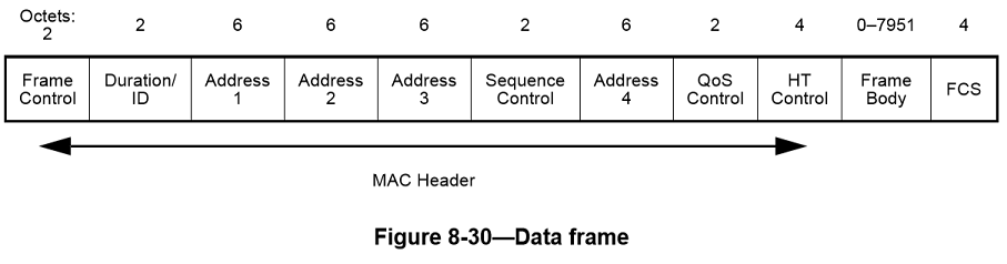
Data frame format
The format of a data frame is defined in Figure8-30. The Frame Control, Duration/ID, Address 1, Address 2, Address 3, and Sequence Control fields are present in all data frame subtypes. The presence of the Address 4 field is determined by the setting of the To DS and From DS subfields of the Frame Control field (see below). The QoS Control field is present when the QoS subfield of the Subtype field is set to 1.
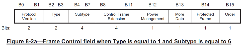
WiGig Frame Control Field format when type=1 and subtype=6
When the value of the Type subfield is equal to 1 and the value of the Subtype subfield is equal to 6, the remaining subfields within the Frame Control field are the following: Control Frame Extension, Power Management, More Data, Protected Frame, and Order. In this case, the format of the Frame Control field is illustrated in Figure 8-2a.
WPA3 Support
WPA3-SAE Mode
When a BSS is configured in WPA3-SAE Mode, PMF shall be set to required (MFPR bit in the RSN Capabilities field shall be set to 1 in the RSNE transmitted by the AP). A WPA3-SAE STA shall negotiate PMF when associating to an AP using WPA3-SAE Mode WPA3-SAE Transition Mode
When WPA2-PSK and WPA3-SAE are configured on the same BSS (mixed mode), PMF shall be set to capable (MFPC bit shall be set to 1, and MFPR bit shall be set to 0 in the RSN Capabilities field in the RSNE transmitted by the AP)
When WPA2-PSK and WPA3-SAE are configured on the same BSS (mixed mode), the AP shall reject an association for SAE if PMF is not negotiated for that association. A WPA3-SAE STA shall negotiate PMF when associating to an AP using WPA3-SAE Transition Mode
WPA3-Enterprise 192-bit Mode
WPA3-Enterprise 192-bit Mode may be deployed in sensitive enterprise environments to further protect Wi-Fi networks with higher security requirements such as government, defense, and industrial
- WPA3-Enterprise 192-bit Mode requirements
- When WPA3-Enterprise 192-bit Mode is used by an AP, PMF shall be set to required (MFPR bit in the RSN Capabilities field shall be set to 1 in the RSNE transmitted by the AP)
- When WPA3-Enterprise 192-bit Mode is used by a STA, PMF shall be set to required (MFPR bit in the RSN Capabilities field shall be set to 1 in the RSNE transmitted by the STA)
- Permitted EAP cipher suites for use with WPA3-Enterprise 192-bit Mode are:
- TLS_ECDHE_ECDSA_WITH_AES_256_GCM_SHA384
- ECDHE and ECDSA using the 384-bit prime modulus curve P-384
- TLS_ECDHE_RSA_WITH_AES_256_GCM_SHA384
- ECDHE using the 384-bit prime modulus curve P-384
- RSA ≥ 3072-bit modulus
- TLS_DHE_RSA_WITH_AES_256_GCM_SHA384
- RSA ≥ 3072-bit modulus
- DHE ≥ 3072-bit modulus
For API Documentation:
For Additional Documentation:
The source code contained or described herein and all documents related to the source code (herein called "Material") are owned by John Peter Greninger and Sheila Rocha Greninger. Title to the Material remains with John Peter Greninger and Sheila Rocha Greninger. The Material contains trade secrets and proprietary and confidential information of John Peter Greninger and Sheila Rocha Greninger. The Material is protected by worldwide copyright and trade secret laws and treaty provisions. No part of the Material may be used, copied, reproduced, modified, published, uploaded, posted, transmitted, distributed, or disclosed in any way without prior express written consent of John Peter Greninger and Sheila Rocha Greninger (both are required)
No license under any patent, copyright, trade secret, or other intellectual property right is granted to or conferred upon you by disclosure or delivery of the Materials, either expressly, by implication, inducement, estoppel, or otherwise. Any license under such intellectual property rights must be express and approved by John Peter Greninger and Sheila Rocha Greninger in writing
Licensing information can be found at www.protocolpp.com/license with use of the binary forms permitted provided that the following conditions are met:
- Redistributions in binary form must reproduce the above copyright notice, this list of conditions and the following disclaimer in the documentation and/or other materials provided with the distribution
- Any and all modifications must be returned to John Peter Greninger at GitHub.com https://github.com/jpgreninger/protocolpp for evaluation. Inclusion of modifications in the source code shall be determined solely by John Peter Greninger. Failure to provide modifications shall render this license NULL and VOID and revoke any rights to use of Protocol++®
- Commercial use (incidental or not) requires a fee-based license obtainable at www.protocolpp.com/shop
- Academic or research use requires prior written and notarized permission from John Peter and Sheila Rocha Greninger
Use of the source code requires purchase of the source code. Source code can be purchased at www.protocolpp.com/shop
- US Copyrights at https://www.copyright.gov/
- TXu002059872 (Version 1.0.0)
- TXu002066632 (Version 1.2.7)
- TXu002082674 (Version 1.4.0)
- TXu002097880 (Version 2.0.0)
- TXu002169236 (Version 3.0.1)
- TXu002182417 (Version 4.0.0)
- TXu002219402 (Version 5.0.0)
- TXu002272076 (Version 5.2.1)
- TXu002383571 (Version 5.4.3)
The name of its contributor may not be used to endorse or promote products derived from this software without specific prior written permission and licensing
THIS SOFTWARE IS PROVIDED BY THE COPYRIGHT HOLDER AND CONTRIBUTOR "AS IS" AND ANY EXPRESS OR IMPLIED WARRANTIES, INCLUDING, BUT NOT LIMITED TO, THE IMPLIED WARRANTIES OF MERCHANTABILITY AND FITNESS FOR A PARTICULAR PURPOSE ARE DISCLAIMED. IN NO EVENT SHALL THE COPYRIGHT OWNER OR CONTRIBUTORS BE LIABLE FOR ANY DIRECT, INDIRECT, INCIDENTAL, SPECIAL, EXEMPLARY, OR CONSEQUENTIAL DAMAGES (INCLUDING, BUT NOT LIMITED TO, PROCUREMENT OF SUBSTITUTE GOODS OR SERVICES; LOSS OF USE, DATA, OR PROFITS; OR BUSINESS INTERRUPTION) HOWEVER CAUSED AND ON ANY THEORY OF LIABILITY, WHETHER IN CONTRACT, STRICT LIABILITY, OR TORT (INCLUDING NEGLIGENCE OR OTHERWISE) ARISING IN ANY WAY OUT OF THE USE OF THIS SOFTWARE, EVEN IF ADVISED OF THE POSSIBILITY OF SUCH DAMAGE
The documentation for this class was generated from the following file:
- include/jwifisa.h