#include "include/jipsec.h"
Detailed Description
Encapsulating Security Payload (ESP)
(See RFC4303 for complete details)
The (outer) protocol header (IPv4, IPv6, or Extension) that immediately precedes the ESP header SHALL contain the value 50 in its Protocol (IPv4) or Next Header (IPv6, Extension) field (see IANA web page at http://www.iana.org/assignments/protocol-numbers). Figure 1 illustrates the top-level format of an ESP packet. The packet begins with two 4-byte fields (Security Parameters Index (SPI) and Sequence Number). Following these fields is the Payload Data, which has substructure that depends on the choice of encryption algorithm and mode, and on the use of TFC padding, which is examined in more detail later. Following the Payload Data are Padding and Pad Length fields, and the Next Header field. The optional Integrity Check Value (ICV) field completes the packet.
The (transmitted) ESP trailer consists of the Padding, Pad Length, and Next Header fields. Additional, implicit ESP trailer data (which is not transmitted) is included in the integrity computation, as described below.
If the integrity service is selected, the integrity computation encompasses the SPI, Sequence Number, Payload Data, and the ESP trailer (explicit and implicit).
If the confidentiality service is selected, the ciphertext consists of the Payload Data (except for any cryptographic synchronization data that may be included) and the (explicit) ESP trailer.
As noted above, the Payload Data may have substructure. An encryption algorithm that requires an explicit Initialization Vector (IV), e.g., Cipher Block Chaining (CBC) mode, often prefixes the Payload Data to be protected with that value. Some algorithm modes combine encryption and integrity into a single operation; this document refers to such algorithm modes as "combined mode algorithms". Accommodation of combined mode algorithms requires that the algorithm explicitly describe the payload substructure used to convey the integrity data.
Some combined mode algorithms provide integrity only for data that is encrypted, whereas others can provide integrity for some additional data that is not encrypted for transmission. Because the SPI and Sequence Number fields require integrity as part of the integrity service, and they are not encrypted, it is necessary to ensure that they are afforded integrity whenever the service is selected, regardless of the style of combined algorithm mode employed.
When any combined mode algorithm is employed, the algorithm itself is expected to return both decrypted plaintext and a pass/fail indication for the integrity check. For combined mode algorithms, the ICV that would normally appear at the end of the ESP packet (when integrity is selected) may be omitted. When the ICV is omitted and integrity is selected, it is the responsibility of the combined mode algorithm to encode within the Payload Data an ICV-equivalent means of verifying the integrity of the packet.
If a combined mode algorithm offers integrity only to data that is encrypted, it will be necessary to replicate the SPI and Sequence Number as part of the Payload Data.
Finally, a new provision is made to insert padding for traffic flow confidentiality after the Payload Data and before the ESP trailer. Figure 2 illustrates this substructure for Payload Data. (Note: This diagram shows bits-on-the-wire. So even if extended sequence numbers are being used, only 32 bits of the Sequence Number will be transmitted (see Section 2.2.1).)
If a combined algorithm mode is employed, the explicit ICV shown in Figures 1 and 2 may be omitted (see Section 3.3.2.2 below). Because algorithms and modes are fixed when an SA is established, the detailed format of ESP packets for a given SA (including the Payload Data substructure) is fixed, for all traffic on the SA.
The tables below refer to the fields in the preceding figures and illustrate how several categories of algorithmic options, each with a different processing model, affect the fields noted above. The processing details are described in later sections.
The following subsections describe the fields in the header format. "Optional" means that the field is omitted if the option is not selected, i.e., it is present in neither the packet as transmitted nor as formatted for computation of an ICV (see Section 2.7). Whether or not an option is selected is determined as part of Security Association (SA) establishment. Thus, the format of ESP packets for a given SA is fixed, for the duration of the SA. In contrast, "mandatory" fields are always present in the ESP packet format, for all SAs.
Note: All of the cryptographic algorithms used in IPsec expect their input in canonical network byte order (see Appendix of RFC 791 [Pos81]) and generate their output in canonical network byte order. IP packets are also transmitted in network byte order.
ESP does not contain a version number, therefore if there are concerns about backward compatibility, they MUST be addressed by using a signaling mechanism between the two IPsec peers to ensure compatible versions of ESP (e.g., Internet Key Exchange (IKEv2) [Kau05]) or an out-of-band configuration mechanism.
Security Parameters Index (SPI)
The SPI is an arbitrary 32-bit value that is used by a receiver to identify the SA to which an incoming packet is bound. The SPI field is mandatory
For a unicast SA, the SPI can be used by itself to specify an SA, or it may be used in conjunction with the IPsec protocol type (in this case ESP). Because the SPI value is generated by the receiver for a unicast SA, whether the value is sufficient to identify an SA by itself or whether it must be used in conjunction with the IPsec protocol value is a local matter. This mechanism for mapping inbound traffic to unicast SAs MUST be supported by all ESP implementations.
If an IPsec implementation supports multicast, then it MUST support multicast SAs using the algorithm below for mapping inbound IPsec datagrams to SAs. Implementations that support only unicast traffic need not implement this de-multiplexing algorithm.
In many secure multicast architectures (e.g., [RFC3740]), a central Group Controller/Key Server unilaterally assigns the group security association's SPI. This SPI assignment is not negotiated or coordinated with the key management (e.g., IKE) subsystems that reside in the individual end systems that comprise the group. Consequently, it is possible that a group security association and a unicast security association can simultaneously use the same SPI. A multicast-capable IPsec implementation MUST correctly de-multiplex inbound traffic even in the context of SPI collisions.
Each entry in the Security Association Database (SAD) [Ken-Arch] must indicate whether the SA lookup makes use of the destination, or destination and source, IP addresses, in addition to the SPI. For multicast SAs, the protocol field is not employed for SA lookups. For each inbound, IPsec-protected packet, an implementation must conduct its search of the SAD such that it finds the entry that matches the "longest" SA identifier. In this context, if two or more SAD entries match based on the SPI value, then the entry that also matches based on destination, or destination and source, address comparison (as indicated in the SAD entry) is the "longest" match. This implies a logical ordering of the SAD search as follows:
- Search the SAD for a match on {SPI, destination address, source address}. If an SAD entry matches, then process the inbound ESP packet with that matching SAD entry. Otherwise, proceed to step 2.
- Search the SAD for a match on {SPI, destination address}. If the SAD entry matches, then process the inbound ESP packet with that matching SAD entry. Otherwise, proceed to step 3.
- Search the SAD for a match on only {SPI} if the receiver has chosen to maintain a single SPI space for AH and ESP, or on {SPI, protocol} otherwise. If an SAD entry matches, then process the inbound ESP packet with that matching SAD entry. Otherwise, discard the packet and log an auditable event.
In practice, an implementation MAY choose any method to accelerate this search, although its externally visible behavior MUST be functionally equivalent to having searched the SAD in the above order. For example, a software-based implementation could index into a hash table by the SPI. The SAD entries in each hash table bucket's linked list are kept sorted to have those SAD entries with the longest SA identifiers first in that linked list. Those SAD entries having the shortest SA identifiers are sorted so that they are the last entries in the linked list. A hardware-based implementation may be able to effect the longest match search intrinsically, using commonly available Ternary Content-Addressable Memory (TCAM) features.
The indication of whether source and destination address matching is required to map inbound IPsec traffic to SAs MUST be set either as a side effect of manual SA configuration or via negotiation using an SA management protocol, e.g., IKE or Group Domain of Interpretation (GDOI) [RFC3547]. Typically, Source-Specific Multicast (SSM) [HC03] groups use a 3-tuple SA identifier composed of an SPI, a destination multicast address, and source address. An Any-Source Multicast group SA requires only an SPI and a destination multicast address as an identifier.
The set of SPI values in the range 1 through 255 are reserved by the Internet Assigned Numbers Authority (IANA) for future use; a reserved SPI value will not normally be assigned by IANA unless the use of the assigned SPI value is specified in an RFC. The SPI value of zero (0) is reserved for local, implementation-specific use and MUST NOT be sent on the wire. (For example, a key management implementation might use the zero SPI value to mean "No Security Association Exists" during the period when the IPsec implementation has requested that its key management entity establish a new SA, but the SA has not yet been established.)
Sequence Number
This unsigned 32-bit field contains a counter value that increases by one for each packet sent, i.e., a per-SA packet sequence number. For a unicast SA or a single-sender multicast SA, the sender MUST increment this field for every transmitted packet. Sharing an SA among multiple senders is permitted, though generally not recommended. ESP provides no means of synchronizing packet counters among multiple senders or meaningfully managing a receiver packet counter and window in the context of multiple senders. Thus, for a multi-sender SA, the anti-replay features of ESP are not available (see Sections 3.3.3 and 3.4.3.)
The field is mandatory and MUST always be present even if the receiver does not elect to enable the anti-replay service for a specific SA. Processing of the Sequence Number field is at the discretion of the receiver, but all ESP implementations MUST be capable of performing the processing described in Sections 3.3.3 and 3.4.3. Thus, the sender MUST always transmit this field, but the receiver need not act upon it (see the discussion of Sequence Number Verification in the "Inbound Packet Processing" section (3.4.3) below)
The sender's counter and the receiver's counter are initialized to 0 when an SA is established. (The first packet sent using a given SA will have a sequence number of 1; see Section 3.3.3 for more details on how the sequence number is generated.) If anti-replay is enabled (the default), the transmitted sequence number must never be allowed to cycle. Thus, the sender's counter and the receiver's counter MUST be reset (by establishing a new SA and thus a new key) prior to the transmission of the 2^32nd packet on an SA
Extended (64-bit) Sequence Number
To support high-speed IPsec implementations, Extended Sequence Numbers (ESNs) SHOULD be implemented, as an extension to the current, 32-bit sequence number field. Use of an ESN MUST be negotiated by an SA management protocol. Note that in IKEv2, this negotiation is implicit; the default is ESN unless 32-bit sequence numbers are explicitly negotiated. (The ESN feature is applicable to multicast as well as unicast SAs)
The ESN facility allows use of a 64-bit sequence number for an SA. (See Appendix A, "Extended (64-bit) Sequence Numbers", for details.) Only the low-order 32 bits of the sequence number are transmitted in the plaintext ESP header of each packet, thus minimizing packet overhead. The high-order 32 bits are maintained as part of the sequence number counter by both transmitter and receiver and are included in the computation of the ICV (if the integrity service is selected). If a separate integrity algorithm is employed, the high order bits are included in the implicit ESP trailer, but are not transmitted, analogous to integrity algorithm padding bits. If a combined mode algorithm is employed, the algorithm choice determines whether the high-order ESN bits are transmitted or are included implicitly in the computation. See Section 3.3.2.2 for processing details
Payload Data
Payload Data is a variable-length field containing data (from the original IP packet) described by the Next Header field. The Payload Data field is mandatory and is an integral number of bytes in length. If the algorithm used to encrypt the payload requires cryptographic synchronization data, e.g., an Initialization Vector (IV), then this data is carried explicitly in the Payload field, but it is not called out as a separate field in ESP, i.e., the transmission of an explicit IV is invisible to ESP. (See Figure 2.) Any encryption algorithm that requires such explicit, per-packet synchronization data MUST indicate the length, any structure for such data, and the location of this data as part of an RFC specifying how the algorithm is used with ESP. (Typically, the IV immediately precedes the ciphertext. See Figure 2.) If such synchronization data is implicit, the algorithm for deriving the data MUST be part of the algorithm definition RFC. (If included in the Payload field, cryptographic synchronization data, e.g., an Initialization Vector (IV), usually is not encrypted per se (see Tables 1 and 2), although it sometimes is referred to as being part of the ciphertext.)
Note that the beginning of the next layer protocol header MUST be aligned relative to the beginning of the ESP header as follows. For IPv4, this alignment is a multiple of 4 bytes. For IPv6, the alignment is a multiple of 8 bytes.
With regard to ensuring the alignment of the (real) ciphertext in the presence of an IV, note the following:
- For some IV-based modes of operation, the receiver treats the IV as the start of the ciphertext, feeding it into the algorithm directly. In these modes, alignment of the start of the (real) ciphertext is not an issue at the receiver.
- In some cases, the receiver reads the IV in separately from the ciphertext. In these cases, the algorithm specification MUST address how alignment of the (real) ciphertext is to be achieved
Padding (for Encryption)
Two primary factors require or motivate use of the Padding field.
- If an encryption algorithm is employed that requires the plaintext to be a multiple of some number of bytes, e.g., the block size of a block cipher, the Padding field is used to fill the plaintext (consisting of the Payload Data, Padding, Pad Length, and Next Header fields) to the size required by the algorithm.
- Padding also may be required, irrespective of encryption algorithm requirements, to ensure that the resulting ciphertext terminates on a 4-byte boundary. Specifically, the Pad Length and Next Header fields must be right aligned within a 4-byte word, as illustrated in the ESP packet format figures above, to ensure that the ICV field (if present) is aligned on a 4-byte boundary.
Padding beyond that required for the algorithm or alignment reasons cited above could be used to conceal the actual length of the payload, in support of TFC. However, the Padding field described is too limited to be effective for TFC and thus should not be used for that purpose. Instead, the separate mechanism described below (see Section 2.7) should be used when TFC is required.
The sender MAY add 0 to 255 bytes of padding. Inclusion of the Padding field in an ESP packet is optional, subject to the requirements noted above, but all implementations MUST support generation and consumption of padding.
- For the purpose of ensuring that the bits to be encrypted are a multiple of the algorithm's block size (first bullet above), the padding computation applies to the Payload Data exclusive of any IV, but including the ESP trailer fields. If a combined algorithm mode requires transmission of the SPI and Sequence Number to effect integrity, e.g., replication of the SPI and Sequence Number in the Payload Data, then the replicated versions of these data items, and any associated, ICV-equivalent data, are included in the computation of the pad length. (If the ESN option is selected, the high-order 32 bits of the ESN also would enter into the computation, if the combined mode algorithm requires their transmission for integrity)
- For the purposes of ensuring that the ICV is aligned on a 4-byte boundary (second bullet above), the padding computation applies to the Payload Data inclusive of the IV, the Pad Length, and Next Header fields. If a combined mode algorithm is used, any replicated data and ICV-equivalent data are included in the Payload Data covered by the padding computation
If Padding bytes are needed but the encryption algorithm does not specify the padding contents, then the following default processing MUST be used. The Padding bytes are initialized with a series of (unsigned, 1-byte) integer values. The first padding byte appended to the plaintext is numbered 1, with subsequent padding bytes making up a monotonically increasing sequence: 1, 2, 3, ... When this padding scheme is employed, the receiver SHOULD inspect the Padding field. (This scheme was selected because of its relative simplicity, ease of implementation in hardware, and because it offers limited protection against certain forms of "cut and paste" attacks in the absence of other integrity measures, if the receiver checks the padding values upon decryption.)
If an encryption or combined mode algorithm imposes constraints on the values of the bytes used for padding, they MUST be specified by the RFC defining how the algorithm is employed with ESP. If the algorithm requires checking of the values of the bytes used for padding, this too MUST be specified in that RFC.
Pad Length
The Pad Length field indicates the number of pad bytes immediately preceding it in the Padding field. The range of valid values is 0 to 255, where a value of zero indicates that no Padding bytes are present. As noted above, this does not include any TFC padding bytes. The Pad Length field is mandatory
Next Header
The Next Header is a mandatory, 8-bit field that identifies the type of data contained in the Payload Data field, e.g., an IPv4 or IPv6 packet, or a next layer header and data. The value of this field is chosen from the set of IP Protocol Numbers defined on the web page of the IANA, e.g., a value of 4 indicates IPv4, a value of 41 indicates IPv6, and a value of 6 indicates TCP
To facilitate the rapid generation and discarding of the padding traffic in support of traffic flow confidentiality (see Section 2.4), the protocol value 59 (which means "no next header") MUST be used to designate a "dummy" packet. A transmitter MUST be capable of generating dummy packets marked with this value in the next protocol field, and a receiver MUST be prepared to discard such packets, without indicating an error. All other ESP header and trailer fields (SPI, Sequence Number, Padding, Pad Length, Next Header, and ICV) MUST be present in dummy packets, but the plaintext portion of the payload, other than this Next Header field, need not be well-formed, e.g., the rest of the Payload Data may consist of only random bytes. Dummy packets are discarded without prejudice
Implementations SHOULD provide local management controls to enable the use of this capability on a per-SA basis. The controls should allow the user to specify if this feature is to be used and also provide parametric controls; for example, the controls might allow an administrator to generate random-length or fixed-length dummy packets
DISCUSSION: Dummy packets can be inserted at random intervals to mask the absence of actual traffic. One can also "shape" the actual traffic to match some distribution to which dummy traffic is added as dictated by the distribution parameters. As with the packet length padding facility for Traffic Flow Security (TFS), the most secure approach would be to generate dummy packets at whatever rate is needed to maintain a constant rate on an SA. If packets are all the same size, then the SA presents the appearance of a constant bit rate data stream, analogous to what a link crypto would offer at layer 1 or 2. However, this is unlikely to be practical in many contexts, e.g., when there are multiple SAs active, because it would imply reducing the allowed bandwidth for a site, based on the number of SAs, and that would undermine the benefits of packet switching. Implementations SHOULD provide controls to enable local administrators to manage the generation of dummy packets for TFC purposes
Traffic Flow Confidentiality (TFC) Padding
As noted above, the Padding field is limited to 255 bytes in length. This generally will not be adequate to hide traffic characteristics relative to traffic flow confidentiality requirements. An optional field, within the payload data, is provided specifically to address the TFC requirement
An IPsec implementation SHOULD be capable of padding traffic by adding bytes after the end of the Payload Data, prior to the beginning of the Padding field. However, this padding (hereafter referred to as TFC padding) can be added only if the Payload Data field contains a specification of the length of the IP datagram. This is always true in tunnel mode, and may be true in transport mode depending on whether the next layer protocol (e.g., IP, UDP, ICMP) contains explicit length information. This length information will enable the receiver to discard the TFC padding, because the true length of the Payload Data will be known. (ESP trailer fields are located by counting back from the end of the ESP packet.) Accordingly, if TFC padding is added, the field containing the specification of the length of the IP datagram MUST NOT be modified to reflect this padding. No requirements for the value of this padding are established by this standard
In principle, existing IPsec implementations could have made use of this capability previously, in a transparent fashion. However, because receivers may not have been prepared to deal with this padding, the SA management protocol MUST negotiate this service prior to a transmitter employing it, to ensure backward compatibility. Combined with the convention described in Section 2.6 above, about the use of protocol ID 59, an ESP implementation is capable of generating dummy and real packets that exhibit much greater length variability, in support of TFC
Implementations SHOULD provide local management controls to enable the use of this capability on a per-SA basis. The controls should allow the user to specify if this feature is to be used and also provide parametric controls for the feature
Integrity Check Value (ICV)
The Integrity Check Value is a variable-length field computed over the ESP header, Payload, and ESP trailer fields. Implicit ESP trailer fields (integrity padding and high-order ESN bits, if applicable) are included in the ICV computation. The ICV field is optional. It is present only if the integrity service is selected and is provided by either a separate integrity algorithm or a combined mode algorithm that uses an ICV. The length of the field is specified by the integrity algorithm selected and associated with the SA. The integrity algorithm specification MUST specify the length of the ICV and the comparison rules and processing steps for validation
Encapsulating Security Protocol Processing
ESP Header Location
ESP may be employed in two ways: transport mode or tunnel mode.
Transport Mode Processing
In transport mode, ESP is inserted after the IP header and before a next layer protocol, e.g., TCP, UDP, ICMP, etc. In the context of IPv4, this translates to placing ESP after the IP header (and any options that it contains), but before the next layer protocol. (If AH is also applied to a packet, it is applied to the ESP header, Payload, ESP trailer, and ICV, if present.) (Note that the term "transport" mode should not be misconstrued as restricting its use to TCP and UDP.) The following diagram illustrates ESP transport mode positioning for a typical IPv4 packet, on a "before and after" basis. (This and subsequent diagrams in this section show the ICV field, the presence of which is a function of the security services and the algorithm/mode selected)
In the IPv6 context, ESP is viewed as an end-to-end payload, and thus should appear after hop-by-hop, routing, and fragmentation extension headers. Destination options extension header(s) could appear before, after, or both before and after the ESP header depending on the semantics desired. However, because ESP protects only fields after the ESP header, it generally will be desirable to place the destination options header(s) after the ESP header. The following diagram illustrates ESP transport mode positioning for a typical IPv6 packet
Note that in transport mode, for "bump-in-the-stack" or "bump-in- the-wire" implementations, as defined in the Security Architecture document, inbound and outbound IP fragments may require an IPsec implementation to perform extra IP reassembly/fragmentation in order to both conform to this specification and provide transparent IPsec support. Special care is required to perform such operations within these implementations when multiple interfaces are in use
Tunnel Mode Processing
In tunnel mode, the "inner" IP header carries the ultimate (IP) source and destination addresses, while an "outer" IP header contains the addresses of the IPsec "peers", e.g., addresses of security gateways. Mixed inner and outer IP versions are allowed, i.e., IPv6 over IPv4 and IPv4 over IPv6. In tunnel mode, ESP protects the entire inner IP packet, including the entire inner IP header. The position of ESP in tunnel mode, relative to the outer IP header, is the same as for ESP in transport mode. The following diagram illustrates ESP tunnel mode positioning for typical IPv4 and IPv6 packets
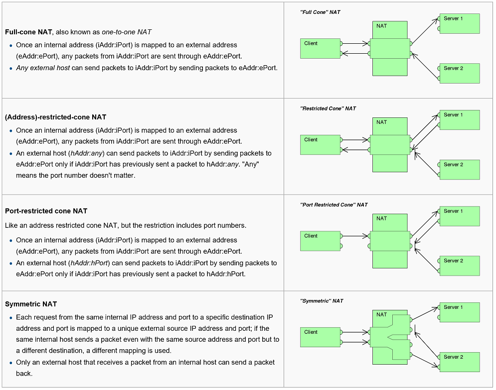
Network Address Translation Transversal (NAT)
See https://en.wikipedia.org/wiki/Network_address_translation
See https://www.rfc-editor.org/rfc/pdfrfc/rfc3948.txt.pdf
Network address translation (NAT) is a method of remapping one IP address space into another by modifying network address information in Internet Protocol (IP) datagram packet headers while they are in transit across a traffic routing device.[1] The technique was originally used for ease of rerouting traffic in IP networks without renumbering every host. It has become a popular and essential tool in conserving global address space allocations in face of IPv4 address exhaustion by sharing one Internet-routable IP address of a NAT gateway for an entire private network
Methodology
The original use of network address translation consisted of mapping every address of one address space to a corresponding address in another space, such as when an enterprise changed Internet service providers without having a facility to announce a public route to the network. In the face of the foreseeable global IP address space exhaustion, NAT was increasingly used since the late 1990s in conjunction with IP masquerading, which is a technique that hides an entire IP address space, usually consisting of private network IP addresses (RFC 1918), behind a single IP address in another, usually public address space. This mechanism is implemented in a routing device that uses stateful translation tables to map the "hidden" addresses into a single IP address and readdresses the outgoing IP packets on exit so they appear to originate from the routing device. In the reverse communications path, responses are mapped back to the originating IP addresses using the rules ("state") stored in the translation tables. The translation table rules established in this fashion are flushed after a short period unless new traffic refreshes their state to prevent port exhaustion and free state table resources
The method enables communication through the router only when the conversation originates in the masqueraded network since this establishes the translation tables. For example, a web browser in the masqueraded network can browse a website outside, but a web browser outside could not browse a website hosted within the masqueraded network. However, most NAT devices today allow the network administrator to configure translation table entries for permanent use. This feature is often referred to as "static NAT" or port forwarding and allows traffic originating in the "outside" network to reach designated hosts in the masqueraded network
Because of the popularity of this technique to conserve IPv4 address space, the term NAT has become virtually synonymous with the method of IP masquerading
As network address translation modifies the IP address information in packets, it has serious consequences on the quality of Internet connectivity and requires careful attention to the details of its implementation. NAT implementations vary widely in their specific behavior in various addressing cases and their effect on network traffic. The specifics of NAT behavior is not commonly documented by vendors of equipment containing implementations.[2]
Basic NAT
The simplest type of NAT provides a one-to-one translation of IP addresses. RFC 2663 refers to this type of NAT as basic NAT; it is often also called a one-to-one NAT. In this type of NAT, only the IP addresses, IP header checksum and any higher level checksums that include the IP address are changed. Basic NATs can be used to interconnect two IP networks that have incompatible addressing
One-to-many NAT
The majority of NATs map multiple private hosts to one publicly exposed IP address. In a typical configuration, a local network uses one of the designated "private" IP address subnets (RFC 1918). A router on that network has a private address in that address space. The router is also connected to the Internet with a "public" address assigned by an Internet service provider. As traffic passes from the local network to the Internet, the source address in each packet is translated on the fly from a private address to the public address. The router tracks basic data about each active connection (particularly the destination address and port). When a reply returns to the router, it uses the connection tracking data it stored during the outbound phase to determine the private address on the internal network to which to forward the reply
One of the benefits of this is that it is a practical solution to the impending exhaustion of the IPv4 address space. Even large networks can be connected to the Internet with a single IP address. The more common arrangement is having computers that require end-to-end connectivity supplied with a routable IP address, while having others that do not provide services to outside users behind NAT with only a few IP addresses used to enable Internet access
All datagram packets on IP networks have a source IP address and a destination IP address. Typically packets passing from the private network to the public network will have their source address modified while packets passing from the public network back to the private network will have their destination address modified. More complex configurations are also possible
To avoid ambiguity in how to translate returned packets, further modifications to the packets are required. The vast bulk of Internet traffic is TCP and UDP packets, and for these protocols the port numbers are changed so that the combination of IP address and port information on the returned packet can be unambiguously mapped to the corresponding private address and port information. RFC 2663 uses the term network address and port translation (NAPT) for this type of NAT. Other names include port address translation (PAT), IP masquerading, NAT overload and many-to-one NAT. This is the most common type of NAT and has become synonymous with the term NAT in common usage. This method enables communication through the router only when the conversation originates in the masqueraded network since this establishes the translation tables. For example, a web browser in the masqueraded network can browse a website outside, but a web browser outside could not browse a website hosted within the masqueraded network. However, most NAT devices today allow the network administrator to configure static translation table entries for connections from the external network to the internal masqueraded network. This feature is often referred to as static NAT. It may be implemented in two types: port forwarding which forwards traffic from a specific external port to an internal host on a specified port, and designation of a DMZ host which passes all traffic received on the external interface (on any port number) to an internal IP address while preserving the destination port. Both types may be available in the same NAT device
Protocols not based on TCP and UDP require other translation techniques
NAT and TCP/UDP
"Pure NAT", operating on IP alone, may or may not correctly parse protocols that are totally concerned with IP information, such as ICMP, depending on whether the payload is interpreted by a host on the "inside" or "outside" of translation. As soon as the protocol stack is traversed, even with such basic protocols as TCP and UDP, the protocols will break unless NAT takes action beyond the network layer
IP packets have a checksum in each packet header, which provides error detection only for the header. IP datagrams may become fragmented and it is necessary for a NAT to reassemble these fragments to allow correct recalculation of higher-level checksums and correct tracking of which packets belong to which connection
The major transport layer protocols, TCP and UDP, have a checksum that covers all the data they carry, as well as the TCP/UDP header, plus a "pseudo-header" that contains the source and destination IP addresses of the packet carrying the TCP/UDP header. For an originating NAT to pass TCP or UDP successfully, it must recompute the TCP/UDP header checksum based on the translated IP addresses, not the original ones, and put that checksum into the TCP/UDP header of the first packet of the fragmented set of packets. The receiving NAT must recompute the IP checksum on every packet it passes to the destination host, and also recognize and recompute the TCP/UDP header using the retranslated addresses and pseudo-header. This is not a completely solved problem. One solution is for the receiving NAT to reassemble the entire segment and then recompute a checksum calculated across all packets
The originating host may perform Maximum transmission unit (MTU) path discovery to determine the packet size that can be transmitted without fragmentation, and then set the don't fragment (DF) bit in the appropriate packet header field. Of course, this is only a one-way solution, because the responding host can send packets of any size, which may be fragmented before reaching the NAT
Using Advanced Encryption Standard (AES) Counter Mode With IPsec Encapsulating Security Payload (ESP)
See https://tools.ietf.org/pdf/rfc3686.pdf
AES-CTR has many properties that make it an attractive encryption algorithm for in high-speed networking. AES-CTR uses the AES block cipher to create a stream cipher. Data is encrypted and decrypted by XORing with the key stream produced by AES encrypting sequential counter block values AES-CTR is easy to implement, and AES-CTR can be pipelined and parallelized. AES-CTR also supports key stream precomputation
Pipelining is possible because AES has multiple rounds (see section 2.2). A hardware implementation (and some software implementations) can create a pipeline by unwinding the loop implied by this round structure. For example, after a 16-octet block has been input, one round later another 16-octet block can be input, and so on. In AESCTR, these inputs are the sequential counter block values used to generate the key stream. Multiple independent AES encrypt implementations can also be used to improve performance. For example, one could use two AES encrypt implementations in parallel, to process a sequence of counter block values, doubling the effective throughput. The sender can precompute the key stream. Since the key stream does not depend on any data in the packet, the key stream can be precomputed once the nonce and IV are assigned. This precomputation can reduce packet latency. The receiver cannot perform similar precomputation because the IV will not be known before the packet arrives
AES-CTR uses the only AES encrypt operation (for both encryption and decryption), making AES-CTR implementations smaller than implementations of many other AES modes. When used correctly, AES-CTR provides a high level of confidentiality. Unfortunately, AES-CTR is easy to use incorrectly. Being a stream cipher, any reuse of the per-packet value, called the IV, with the same nonce and key is catastrophic. An IV collision immediately leaks information about the plaintext in both packets. For this reason, it is inappropriate to use this mode of operation with static keys. Extraordinary measures would be needed to prevent reuse of an IV value with the static key across power cycles. To be safe, implementations MUST use fresh keys with AES-CTR. The Internet Key Exchange (IKE) protocol can be used to establish fresh keys. IKE can also provide the nonce value. With AES-CTR, it is trivial to use a valid ciphertext to forge other (valid to the decryptor) ciphertexts. Thus, it is equally catastrophic to use AES-CTR without a companion authentication function. Implementations MUST use AES-CTR in conjunction with an authentication function, such as HMAC-SHA-1-96
ESP Payload
The ESP payload is comprised of the IV followed by the ciphertext. The payload field, as defined in [ESP], is structured as shown in Figure 1
Initialization Vector
The AES-CTR IV field MUST be eight octets. The IV MUST be chosen by the encryptor in a manner that ensures that the same IV value is used only once for a given key. The encryptor can generate the IV in any manner that ensures uniqueness. Common approaches to IV generation include incrementing a counter for each packet and linear feedback shift registers (LFSRs). Including the IV in each packet ensures that the decryptor can generate the key stream needed for decryption, even when some packets are lost or reordered
Encrypted Payload
The encrypted payload contains the ciphertext. AES-CTR mode does not require plaintext padding. However, ESP does require padding to 32-bit word-align the authentication data. The padding, Pad Length, and the Next Header MUST be concatenated with the plaintext before performing encryption, as described in [ESP]
Authentication Data
Since it is trivial to construct a forgery AES-CTR ciphertext from a valid AES-CTR ciphertext, AES-CTR implementations MUST employ a non-NULL ESP authentication method. HMAC-SHA-1-96 [HMAC-SHA] is a likely choice
Counter Block Format
Each packet conveys the IV that is necessary to construct the sequence of counter blocks used to generate the key stream necessary to decrypt the payload. The AES counter block cipher block is 128 bits. Figure 2 shows the format of the counter block
The components of the counter block are as follows:
Nonce
The Nonce field is 32 bits. As the name implies, the nonce is a single use value. That is, a fresh nonce value MUST be assigned for each security association. It MUST be assigned at the beginning of the security association. The nonce value need not be secret, but it MUST be unpredictable prior to the beginning of the security association
Initialization Vector
The IV field is 64 bits. As described in section 3.1, the IV MUST be chosen by the encryptor in a manner that ensures that the same IV value is used only once for a given key.
Block Counter
The block counter field is the least significant 32 bits of the counter block. The block counter begins with the value of one, and it is incremented to generate subsequent portions of the key stream. The block counter is a 32-bit big-endian integer value. Using the encryption process described in section 2.1, this construction permits each packet to consist of up to:

This construction can produce enough key stream for each packet sufficient to handle any IPv6 jumbogram
Keying Material and Nonces
As described in section 2.1, implementations MUST use fresh keys with AES-CTR. IKE can be used to establish fresh keys. This section describes the conventions for obtaining the unpredictable nonce value from IKE. Note that this convention provides a nonce value that is secret as well as unpredictable.
IKE makes use of a pseudo-random function (PRF) to derive keying material. The PRF is used iteratively to derive keying material of arbitrary size, called KEYMAT. Keying material is extracted from the output string without regard to boundaries. The size of the requested KEYMAT MUST be four octets longer than is needed for the associated AES key. The keying material is used as follows:
AES-CTR with a 128 bit key
The KEYMAT requested for each AES-CTR key is 20 octets. The first 16 octets are the 128-bit AES key, and the remaining four octets are used as the nonce value in the counter block.
AES-CTR with a 192 bit key
The KEYMAT requested for each AES-CTR key is 28 octets. The first 24 octets are the 192-bit AES key, and the remaining four octets are used as the nonce value in the counter block.
AES-CTR with a 256 bit key
The KEYMAT requested for each AES-CTR key is 36 octets. The first 32 octets are the 256-bit AES key, and the remaining four octets are used as the nonce value in the counter block
The Use of Galois/Counter Mode (GCM) in IPsec Encapsulating Security Payload (ESP)
See https://tools.ietf.org/pdf/rfc4106.pdf
GCM is a block cipher mode of operation providing both confidentiality and data origin authentication. The GCM authenticated encryption operation has four inputs: a secret key, an initialization vector (IV), a plaintext, and an input for additional authenticated data (AAD). It has two outputs, a ciphertext whose length is identical to the plaintext, and an authentication tag. In the following, we describe how the IV, plaintext, and AAD are formed from the ESP fields, and how the ESP packet is formed from the ciphertext and authentication tag.
ESP also defines an IV. For clarity, we refer to the AES-GCM IV as a nonce in the context of AES-GCM-ESP. The same nonce and key combination MUST NOT be used more than once.
Because reusing an nonce/key combination destroys the security guarantees of AES-GCM mode, it can be difficult to use this mode securely when using statically configured keys. For safety’s sake, implementations MUST use an automated key management system, such as the Internet Key Exchange (IKE) [RFC2409], to ensure that this requirement is met.
ESP Payload Data
The ESP Payload Data is comprised of an eight-octet initialization vector (IV), followed by the ciphertext. The payload field, as defined in [RFC2406], is structured as shown in Figure 1, along with the ICV associated with the payload.
Initialization Vector (IV)
The AES-GCM-ESP IV field MUST be eight octets. For a given key, the IV MUST NOT repeat. The most natural way to implement this is with a counter, but anything that guarantees uniqueness can be used, such as a linear feedback shift register (LFSR). Note that the encrypter can use any IV generation method that meets the uniqueness requirement, without coordinating with the decrypter.
Ciphertext
The plaintext input to AES-GCM is formed by concatenating the plaintext data described by the Next Header field with the Padding, the Pad Length, and the Next Header field. The Ciphertext field consists of the ciphertext output from the AES-GCM algorithm. The length of the ciphertext is identical to that of the plaintext.
Implementations that do not seek to hide the length of the plaintext SHOULD use the minimum amount of padding required, which will be less than four octets.
Nonce Format
The nonce passed to the GCM-AES encryption algorithm has the following layout:
The components of the nonce are as follows:
Salt
The salt field is a four-octet value that is assigned at the beginning of the security association, and then remains constant for the life of the security association. The salt SHOULD be unpredictable (i.e., chosen at random) before it is selected, but need not be secret. We describe how to set the salt for a Security Association established via the Internet Key Exchange in Section 8.1.
Initialization Vector
The IV field is described in Section 3.1.
AAD Construction
The authentication of data integrity and data origin for the SPI and (Extended) Sequence Number fields is provided without encryption. This is done by including those fields in the AES-GCM Additional Authenticated Data (AAD) field. Two formats of the AAD are defined: one for 32-bit sequence numbers, and one for 64-bit extended sequence numbers. The format with 32-bit sequence numbers is shown in Figure 3, and the format with 64-bit extended sequence numbers is shown in Figure 4.
Integrity Check Value (ICV)
The ICV consists solely of the AES-GCM Authentication Tag. Implementations MUST support a full-length 16-octet ICV, and MAY support 8 or 12 octet ICVs, and MUST NOT support other ICV lengths. Although ESP does not require that an ICV be present, AES-GCM-ESP intentionally does not allow a zero-length ICV. This is because GCM provides no integrity protection whatsoever when used with a zero length Authentication Tag.
Packet Expansion
The IV adds an additional eight octets to the packet, and the ICV adds an additional 8, 12, or 16 octets. These are the only sources of packet expansion, other than the 10-13 octets taken up by the ESP SPI, Sequence Number, Padding, Pad Length, and Next Header fields (if the minimal amount of padding is used).
IKE Conventions
This section describes the conventions used to generate keying material and salt values, for use with AES-GCM-ESP, using the Internet Key Exchange (IKE) [RFC2409] protocol. The identifiers and attributes needed to negotiate a security association using AES-GCM ESP are also defined.
Keying Material and Salt Values
IKE makes use of a pseudo-random function (PRF) to derive keying material. The PRF is used iteratively to derive keying material of arbitrary size, called KEYMAT. Keying material is extracted from the output string without regard to boundaries.
The size of the KEYMAT for the AES-GCM-ESP MUST be four octets longer than is needed for the associated AES key. The keying material is used as follows:
AES-GCM-ESP with a 128 bit key
The KEYMAT requested for each AES-GCM key is 20 octets. The first 16 octets are the 128-bit AES key, and the remaining four octets are used as the salt value in the nonce.
AES-GCM-ESP with a 192 bit key
The KEYMAT requested for each AES-GCM key is 28 octets. The first 24 octets are the 192-bit AES key, and the remaining four octets are used as the salt value in the nonce.
AES-GCM-ESP with a 256 bit key
The KEYMAT requested for each AES GCM key is 36 octets. The first 32 octets are the 256-bit AES key, and the remaining four octets are used as the salt value in the nonce.
Using Advanced Encryption Standard (AES) CCM Mode with IPsec Encapsulating Security Payload (ESP)
See https://www.rfc-editor.org/rfc/pdfrfc/rfc4309.txt.pdf
AES CCM Mode
CCM is a generic authenticate-and-encrypt block cipher mode [CCM]. In this specification, CCM is used with the AES [AES] block cipher. AES CCM has two parameters:
M
M indicates the size of the integrity check value (ICV). CCM defines values of 4, 6, 8, 10, 12, 14, and 16 octets; However, to maintain alignment and provide adequate security, only the values that are a multiple of four and are at least eight are permitted. Implementations MUST support M values of 8 octets and 16 octets, and implementations MAY support an M value of 12 octets.
L
L indicates the size of the length field in octets. CCM defines values of L between 2 octets and 8 octets. This specification only supports L = 4. Implementations MUST support an L value of 4 octets, which accommodates a full Jumbogram [JUMBO]; however, the length includes all of the encrypted data, which also includes the ESP Padding, Pad Length, and Next Header fields.
There are four inputs to CCM originator processing:
key
A single key is used to calculate the ICV using CBC-MAC and to perform payload encryption using counter mode. AES supports key sizes of 128 bits, 192 bits, and 256 bits. The default key size is 128 bits, and implementations MUST support this key size. Implementations MAY also support key sizes of 192 bits and 256 bits.
nonce
The size of the nonce depends on the value selected for the parameter L. It is 15-L octets. Implementations MUST support a nonce of 11 octets. The construction of the nonce is described in Section 4.
payload
The payload of the ESP packet. The payload MUST NOT be longer than 4,294,967,295 octets, which is the maximum size of a Jumbogram [JUMBO]; however, the ESP Padding, Pad Length, and Next Header fields are also part of the payload.
AAD
CCM provides data integrity and data origin authentication for some data outside the payload. CCM does not allow additional authenticated data (AAD) to be longer than 18,446,744,073,709,551,615 octets. The ICV is computed from the ESP header, Payload, and ESP trailer fields, which is significantly smaller than the CCM-imposed limit. The construction of the AAD described in Section 5.
AES CCM requires the encryptor to generate a unique per-packet value and to communicate this value to the decryptor. This per-packet value is one of the component parts of the nonce, and it is referred to as the initialization vector (IV). The same IV and key combination MUST NOT be used more than once. The encryptor can generate the IV in any manner that ensures uniqueness. Common approaches to IV generation include incrementing a counter for each packet and linear feedback shift registers (LFSRs).
AES CCM employs counter mode for encryption. As with any stream cipher, reuse of the same IV value with the same key is catastrophic. An IV collision immediately leaks information about the plaintext in both packets. For this reason, it is inappropriate to use this CCM with statically configured keys. Extraordinary measures would be needed to prevent reuse of an IV value with the static key across power cycles. To be safe, implementations MUST use fresh keys with AES CCM. The Internet Key Exchange (IKE) [IKE] protocol or IKEv2 [IKEv2] can be used to establish fresh keys.
ESP Payload
The ESP payload is composed of the IV followed by the ciphertext. The payload field, as defined in [ESP], is structured as shown in Figure 1.
Initialization Vector (IV)
The AES CCM IV field MUST be eight octets. The IV MUST be chosen by the encryptor in a manner that ensures that the same IV value is used only once for a given key. The encryptor can generate the IV in any manner that ensures uniqueness. Common/ approaches to IV generation include incrementing a counter for each packet and linear feedback shift registers (LFSRs).
Including the IV in each packet ensures that the decryptor can generate the key stream needed for decryption, even when some datagrams are lost or reordered.
Encrypted Payload
The encrypted payload contains the ciphertext.
AES CCM mode does not require plaintext padding. However, ESP does require padding to 32-bit word-align the authentication data. The Padding, Pad Length, and Next Header fields MUST be concatenated with the plaintext before performing encryption, as described in [ESP]. When padding is required, it MUST be generated and checked in accordance with the conventions specified in [ESP].
Authentication Data
AES CCM provides an encrypted ICV. The ICV provided by CCM is carried in the Authentication Data fields without further encryption. Implementations MUST support ICV sizes of 8 octets and 16 octets. Implementations MAY also support ICV 12 octets.
Nonce Format
Each packet conveys the IV that is necessary to construct the sequence of counter blocks used by counter mode to generate the key stream. The AES counter block is 16 octets. One octet is used for the CCM Flags, and 4 octets are used for the block counter, as specified by the CCM L parameter. The remaining octets are the nonce. These octets occupy the second through the twelfth octets in the counter block. Figure 2 shows the format of the nonce.
The components of the nonce are as follows:
Salt
The salt field is 24 bits. As the name implies, it contains an unpredictable value. It MUST be assigned at the beginning of the security association. The salt value need not be secret, but it MUST NOT be predictable prior to the beginning of the security association.
Initialization Vector
The IV field is 64 bits. As described in Section 3.1, the IV MUST be chosen by the encryptor in a manner that ensures that the same IV value is used only once for a given key.
This construction permits each packet to consist of up to:
 blocks = 4,294,967,296 blocks = 68,719,476,736 octets
This construction provides more key stream for each packet than is needed to handle any IPv6 Jumbogram [JUMBO].
AAD Construction
The data integrity and data origin authentication for the Security Parameters Index (SPI) and (Extended) Sequence Number fields is provided without encrypting them. Two formats are defined: one for 32-bit sequence numbers and one for 64-bit extended sequence numbers. The format with 32-bit sequence numbers is shown in Figure 3, and the format with 64-bit extended sequence numbers is shown in Figure 4.
Sequence Numbers are conveyed canonical network byte order. Extended Sequence Numbers are conveyed canonical network byte order, placing the high-order 32 bits first and the low-order 32 bits second. Canonical network byte order is fully described in RFC 791, Appendix B.
Packet Expansion
The initialization vector (IV) and the integrity check value (ICV) are the only sources of packet expansion. The IV always adds 8 octets to the front of the payload. The ICV is added at the end of the payload, and the CCM parameter M determines the size of the ICV. Implementations MUST support M values of 8 octets and 16 octets, and implementations MAY also support an M value of 12 octets.
IKE Conventions
This section describes the conventions used to generate keying material and salt values for use with AES CCM using the Internet Key Exchange (IKE) [IKE] protocol. The identifiers and attributes needed to negotiate a security association that uses AES CCM are also defined.
Keying Material and Salt Values
As previously described, implementations MUST use fresh keys with AES CCM. IKE can be used to establish fresh keys. This section describes the conventions for obtaining the unpredictable salt value for use in the nonce from IKE. Note that this convention provides a salt value that is secret as well as unpredictable.
IKE makes use of a pseudo-random function (PRF) to derive keying material. The PRF is used iteratively to derive keying material of arbitrary size, called KEYMAT. Keying material is extracted from the output string without regard to boundaries.
The size of KEYMAT MUST be three octets longer than is needed for the associated AES key. The keying material is used as follows:
AES CCM with a 128-bit key
The KEYMAT requested for each AES CCM key is 19 octets. The first 16 octets are the 128-bit AES key, and the remaining three octets are used as the salt value in the counter block.
AES CCM with a 192-bit key
The KEYMAT requested for each AES CCM key is 27 octets. The first 24 octets are the 192-bit AES key, and the remaining three octets are used as the salt value in the counter block.
AES CCM with a 256-bit key
The KEYMAT requested for each AES CCM key is 35 octets. The first 32 octets are the 256-bit AES key, and the remaining three octets are used as the salt value in the counter block.
ChaCha20, Poly1305, and Their Use in the Internet Key Exchange Protocol (IKE) and IPsec
The Advanced Encryption Standard (AES) [FIPS-197] has become the go to algorithm for encryption. It is now the most commonly used algorithm in many areas, including IPsec Virtual Private Networks (VPNs). On most modern platforms, AES is anywhere from four to ten times as fast as the previously popular cipher, Triple Data Encryption Standard (3DES) [SP800-67]. 3DES also uses a 64-bit block; this means that the amount of data that can be encrypted before rekeying is required is limited. These reasons make AES not only the best choice, but the only viable choice for IPsec.
The problem is that if future advances in cryptanalysis reveal a weakness in AES, VPN users will be in an unenviable position. With the only other widely supported cipher for IPsec implementations being the much slower 3DES, it is not feasible to reconfigure IPsec installations away from AES. [Standby-Cipher] describes this issue and the need for a standby cipher in greater detail.
This document proposes the fast and secure ChaCha20 stream cipher as such a standby cipher in an Authenticated Encryption with Associated Data (AEAD) construction with the Poly1305 authenticator for use with the Encapsulated Security Protocol (ESP) [RFC4303] and the Internet Key Exchange Protocol version 2 (IKEv2) [RFC7296]. The algorithms are described in a separate document ([RFC7539]). This document only describes the IPsec-specific things.
ChaCha20 and Poly1305 for ESP
AEAD_CHACHA20_POLY1305 ([RFC7539]) is a combined mode algorithm, or AEAD. Usage follows the AEAD construction in Section 2.8 of RFC 7539:
- The Initialization Vector (IV) is 64 bits and is used as part of the nonce. The IV MUST be unique for each invocation for a particular security association (SA) but does not need to be unpredictable. The use of a counter or a linear feedback shift register (LFSR) is RECOMMENDED.
- A 32-bit Salt is prepended to the 64-bit IV to form the 96-bit nonce. The salt is fixed per SA, and it is not transmitted as part of the ESP packet.
- The encryption key is 256 bits.
- The Internet Key Exchange Protocol generates a bitstring called KEYMAT using a pseudorandom function (PRF). That KEYMAT is divided into keys for encryption, message authentication, and whatever else is needed. The KEYMAT requested for each ChaCha20-Poly1305 key is 36 octets. The first 32 octets are the 256-bit ChaCha20 key, and the remaining 4 octets are used as the Salt value in the nonce.
The ChaCha20 encryption algorithm requires the following parameters:
- a 256-bit key
- a 96-bit nonce
- a 32-bit Initial Block Counter
For ESP, we set these as follows:
- The key is set as mentioned above.
- The 96-bit nonce is formed from a concatenation of the 32-bit Salt and the 64-bit IV, as described above.
- The Initial Block Counter is set to one (1). The reason that one is used for the initial counter rather than zero is that zero is reserved for generating the one-time Poly1305 key (see below).
As the ChaCha20 block function is not applied directly to the plaintext, no padding should be necessary. However, in keeping with the specification in RFC 4303, the plaintext always has a pad length octet and a Next Header octet, and it may require padding octets so as to align the buffer to an integral multiple of 4 octets.
The same key and nonce, along with a block counter of zero, are passed to the ChaCha20 block function, and the top 256 bits of the result are used as the Poly1305 key.
Finally, the Poly1305 function is run on the data to be authenticated, which is, as specified in Section 2.8 of [RFC7539], a concatenation of the following in the order below:
- The Authenticated Additional Data (AAD); see Section 2.1.
- Zero-octet padding that rounds the length up to 16 octets. This is 4 or 8 octets depending on the length of the AAD.
- The ciphertext.
- Zero-octet padding that rounds the total length up to an integral multiple of 16 octets.
- The length of the AAD in octets (as a 64-bit integer encoded in little-endian byte order).
- The length of the ciphertext in octets (as a 64-bit integer encoded in little-endian byte order).
The 128-bit output of Poly1305 is used as the tag. All 16 octets are included in the packet.
- The IV field is 64 bits. It is the final 64 bits of the 96-bit nonce. If the counter method is used for generating unique IVs, then the final 32 bits of the IV will be equal to the Sequence Number field
- The length of the Padding field need not exceed 4 octets. However, neither RFC 4303 nor this specification require using the minimal padding length
- The Integrity Check Value field contains the 16-octet tag
AAD Construction
The construction of the Additional Authenticated Data (AAD) is similar to the one in [RFC4106]. For security associations (SAs) with 32-bit sequence numbers, the AAD is 8 octets: a 4-octet SPI followed by a 4-octet sequence number ordered exactly as it is in the packet. For SAs with an Extended Sequence Number (ESN), the AAD is 12 octets: a 4-octet SPI followed by an 8-octet sequence number as a 64-bit integer in big-endian byte order.
Use in IKEv2
AEAD algorithms can be used in IKE, as described in [RFC5282]. More specifically:
- The Encrypted Payload is as described in Section 3 of RFC 5282.
- The ChaCha20-Poly1305 keying material is derived similarly to ESP: 36 octets are requested for each of SK_ei and SK_er, of which the first 32 form the key and the last 4 form the salt. No octets are requested for SK_ai and SK_ar.
- The IV is 64 bits, as described in Section 2, and is included explicitly in the Encrypted payload.
- The sender SHOULD include no padding and set the Pad Length field to zero. The receiver MUST accept any length of padding
- The AAD is as described in Section 5.1 of RFC 5282, so it is 32 octets (28 for the IKEv2 header plus 4 octets for the encrypted payload header), assuming no unencrypted payloads
Negotiation in IKEv2
When negotiating the ChaCha20-Poly1305 algorithm for use in IKE or IPsec, the value ENCR_CHACHA20_POLY1305 (28) should be used in the transform substructure of the SA payload as the ENCR (type 1) transform ID. As with other AEAD algorithms, INTEG (type 3) transform substructures MUST NOT be specified, or just one INTEG transform MAY be included with value NONE (0).
Security Considerations
The ChaCha20 cipher is designed to provide 256-bit security.
The Poly1305 authenticator is designed to ensure that forged messages are rejected with a probability of 1-(n/(2^102)) for a 16n-octet message, even after sending 2^64 legitimate messages, so it is SUF-CMA (strong unforgeability against chosen-message attacks) in the terminology of [AE].
The most important security consideration in implementing this document is the uniqueness of the nonce used in ChaCha20. The nonce should be selected uniquely for a particular key, but unpredictability of the nonce is not required. Counters and LFSRs are both acceptable ways of generating unique nonces.
Another issue with implementing these algorithms is avoiding side channels. This is trivial for ChaCha20, but requires some care for Poly1305. Considerations for implementations of these algorithms are in [RFC7539].
The Salt value in used nonce construction in ESP and IKEv2 is derived from the keystream, same as the encryption key. It is never transmitted on the wire, but the security of the algorithm does not depend on its secrecy. Thus, implementations that keep keys and other secret material within some security boundary MAY export the Salt from the security boundary. This may be useful if the API provided by the library accepts the nonce as a parameter rather than the IV.
IANA Considerations
IANA has assigned the value 28 as a transform identifier for the algorithm described in this document in the "Transform Type 1 Encryption Algorithm Transform IDs" registry with name ENCR_CHACHA20_POLY1305 and this document as reference for both ESP and IKEv2.
IPsec Cipher and Authentication Synopsis
| Cipher | Key Sizes (bits) | Authentication | MAC Length (bits) |
|---|---|---|---|
| NULL_AUTH | |||
| TDES_CBC | 192 | MD5 | 64, 96, 128 |
| AES_CBC | 128, 192, 256 | SHA1 | 64, 96, 128 |
| AES_CTR | 128, 192, 256 | SHA224 | 64, 96, 128 |
| AES_CCM | 128, 192, 256 | SHA256 | 64, 96, 128 |
| AES_GCM | 128, 192, 256 | SHA384 | 64, 96, 128 |
| CAMELLIA_CBC | 128, 192, 256 | SHA512 | 64, 96, 128 |
| CAMELLIA_CTR | 128, 192, 256 | AES_XCBC_MAC | 64, 96, 128 |
| CAMELLIA_CCM | 128, 192, 256 | AES_CMAC | 64, 96, 128 |
| CAMELLIA_GCM | 128, 192, 256 | SHA3_224 | 64, 96, 128 |
| DES_CBC | 64 | SHA3_256 | 64, 96, 128 |
| SHA3_384 | 64, 96, 128 | ||
| SHA3_512 | 64, 96, 128 | ||
| CHACHA20 | 256 | POLY1305 | 64, 96, 128 |
- NOTE - CHACHA20 and POLY1305 always go together as an AEAD mode and are identified as CHACHA20_POLY1305
- GCM and CCM are also AEAD modes and require no additional authentication mode
For API Documentation:
- See also
- ProtocolPP::jipsec
- ProtocolPP::jipsecsa
- ProtocolPP::jprotocol
- ProtocolPP::jicmp
- ProtocolPP::jicmpsa
- ProtocolPP::jmodes
- ProtocolPP::jreplay
For Additional Documentation:
The source code contained or described herein and all documents related to the source code (herein called "Material") are owned by John Peter Greninger and Sheila Rocha Greninger. Title to the Material remains with John Peter Greninger and Sheila Rocha Greninger. The Material contains trade secrets and proprietary and confidential information of John Peter Greninger and Sheila Rocha Greninger. The Material is protected by worldwide copyright and trade secret laws and treaty provisions. No part of the Material may be used, copied, reproduced, modified, published, uploaded, posted, transmitted, distributed, or disclosed in any way without prior express written consent of John Peter Greninger and Sheila Rocha Greninger (both are required)
No license under any patent, copyright, trade secret, or other intellectual property right is granted to or conferred upon you by disclosure or delivery of the Materials, either expressly, by implication, inducement, estoppel, or otherwise. Any license under such intellectual property rights must be express and approved by John Peter Greninger and Sheila Rocha Greninger in writing
Licensing information can be found at www.protocolpp.com/license with use of the binary forms permitted provided that the following conditions are met:
- Redistributions in binary form must reproduce the above copyright notice, this list of conditions and the following disclaimer in the documentation and/or other materials provided with the distribution
- Any and all modifications must be returned to John Peter Greninger at GitHub.com https://github.com/jpgreninger/protocolpp for evaluation. Inclusion of modifications in the source code shall be determined solely by John Peter Greninger. Failure to provide modifications shall render this license NULL and VOID and revoke any rights to use of Protocol++®
- Commercial use (incidental or not) requires a fee-based license obtainable at www.protocolpp.com/shop
- Academic or research use requires prior written and notarized permission from John Peter and Sheila Rocha Greninger
Use of the source code requires purchase of the source code. Source code can be purchased at www.protocolpp.com/shop
- US Copyrights at https://www.copyright.gov/
- TXu002059872 (Version 1.0.0)
- TXu002066632 (Version 1.2.7)
- TXu002082674 (Version 1.4.0)
- TXu002097880 (Version 2.0.0)
- TXu002169236 (Version 3.0.1)
- TXu002182417 (Version 4.0.0)
- TXu002219402 (Version 5.0.0)
- TXu002272076 (Version 5.2.1)
- TXu002383571 (Version 5.4.3)
The name of its contributor may not be used to endorse or promote products derived from this software without specific prior written permission and licensing
THIS SOFTWARE IS PROVIDED BY THE COPYRIGHT HOLDER AND CONTRIBUTOR "AS IS" AND ANY EXPRESS OR IMPLIED WARRANTIES, INCLUDING, BUT NOT LIMITED TO, THE IMPLIED WARRANTIES OF MERCHANTABILITY AND FITNESS FOR A PARTICULAR PURPOSE ARE DISCLAIMED. IN NO EVENT SHALL THE COPYRIGHT OWNER OR CONTRIBUTORS BE LIABLE FOR ANY DIRECT, INDIRECT, INCIDENTAL, SPECIAL, EXEMPLARY, OR CONSEQUENTIAL DAMAGES (INCLUDING, BUT NOT LIMITED TO, PROCUREMENT OF SUBSTITUTE GOODS OR SERVICES; LOSS OF USE, DATA, OR PROFITS; OR BUSINESS INTERRUPTION) HOWEVER CAUSED AND ON ANY THEORY OF LIABILITY, WHETHER IN CONTRACT, STRICT LIABILITY, OR TORT (INCLUDING NEGLIGENCE OR OTHERWISE) ARISING IN ANY WAY OUT OF THE USE OF THIS SOFTWARE, EVEN IF ADVISED OF THE POSSIBILITY OF SUCH DAMAGE
The documentation for this class was generated from the following file:
- include/jipsec.h