#include "include/jconfident.h"
Detailed Description
- See also
- jmodes for encryption modes of operation
ARC4 Stream Cipher
See https://en.wikipedia.org/wiki/RC4
See http://cypherpunks.venona.com/archive/1994/09/msg00304.html
In cryptography, RC4 (Rivest Cipher 4 also known as ARC4 or ARCFOUR meaning Alleged RC4, see below) is a stream cipher. While it is remarkable for its simplicity and speed in software, multiple vulnerabilities have been discovered in RC4, rendering it insecure. It is especially vulnerable when the beginning of the output keystream is not discarded, or when nonrandom or related keys are used. Particularly problematic uses of RC4 have led to very insecure protocols such as WEP
As of 2015, there is speculation that some state cryptologic agencies may possess the capability to break RC4 when used in the TLS protocol. IETF has published RFC 7465 to prohibit the use of RC4 in TLS; Mozilla and Microsoft have issued similar recommendations
A number of attempts have been made to strengthen RC4, notably Spritz, RC4A, VMPC, and RC4+
History
RC4 was designed by Ron Rivest of RSA Security in 1987. While it is officially termed "Rivest Cipher 4", the RC acronym is alternatively understood to stand for "Ron's Code" (see also RC2, RC5 and RC6)
RC4 was initially a trade secret, but in September 1994 a description of it was anonymously posted to the Cypherpunks mailing list. It was soon posted on the sci.crypt newsgroup, where it was broken within days by Bob Jenkins. From there it spread to many sites on the Internet. The leaked code was confirmed to be genuine as its output was found to match that of proprietary software using licensed RC4. Because the algorithm is known, it is no longer a trade secret. The name RC4 is trademarked, so RC4 is often referred to as ARCFOUR or ARC4 (meaning alleged RC4) to avoid trademark problems. RSA Security has never officially released the algorithm; Rivest has, however, linked to the English Wikipedia article on RC4 in his own course notes in 2008 and confirmed the history of RC4 and its code in a 2014 paper by him
RC4 became part of some commonly used encryption protocols and standards, such as WEP in 1997 and WPA in 2003/2004 for wireless cards; and SSL in 1995 and its successor TLS in 1999, until it was prohibited for all versions of TLS by RFC 7465 in 2015, due to the RC4 attacks weakening or breaking RC4 used in SSL/TLS. The main factors in RC4's success over such a wide range of applications have been its speed and simplicity: efficient implementations in both software and hardware were very easy to develop
Description
RC4 generates a pseudorandom stream of bits (a keystream). As with any stream cipher, these can be used for encryption by combining it with the plaintext using bit-wise exclusive-or; decryption is performed the same way (since exclusive-or with given data is an involution). This is similar to the one-time pad except that generated pseudorandom bits, rather than a prepared stream, are used
To generate the keystream, the cipher makes use of a secret internal state which consists of two parts:
- A permutation of all 256 possible bytes (denoted "S" below)
- Two 8-bit index-pointers (denoted "i" and "j")
The permutation is initialized with a variable length key, typically between 40 and 2048 bits, using the key- scheduling algorithm (KSA). Once this has been completed, the stream of bits is generated using the pseudo-random generation algorithm (PRGA).
Key-scheduling algorithm (KSA)
The key-scheduling algorithm is used to initialize the permutation in the array "S". "keylength" is defined as the number of bytes in the key and can be in the range 1 ≤ keylength ≤ 256, typically between 5 and 16, corresponding to a key length of 40–128 bits. First, the array "S" is initialized to the identity permutation. S is then processed for 256 iterations in a similar way to the main PRGA, but also mixes in bytes of the key at the same time
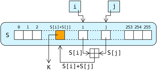
In the above lookup stage of ARC4, the output byte is selected by looking up the values of S[i] and S[j], adding them together modulo 256, and then using the sum as an index into S; S(S[i] + S[j]) is used as a byte of the key stream, K
Pseudo-random generation algorithm (PRGA)
The lookup stage of RC4. The output byte is selected by looking up the values of S[i] and S[j], adding them together modulo 256, and then using the sum as an index into S; S(S[i] + S[j]) is used as a byte of the key stream, K
For as many iterations as are needed, the PRGA modifies the state and outputs a byte of the keystream. In each iteration, the PRGA:
- increments i
- looks up the ith element of S, S[i], and adds that to j
- exchanges the values of S[i] and S[j] then uses the sum S[i] + S[j] (modulo 256) as an index to fetch a third element of S (the keystream value K below)
- then bitwise exclusive ORed (XORed) with the next byte of the message to produce the next byte of either ciphertext or plaintext.
Each element of S is swapped with another element at least once every 256 iterations
Security
Unlike a modern stream cipher (such as those in eSTREAM), RC4 does not take a separate nonce alongside the key. This means that if a single long-term key is to be used to securely encrypt multiple streams, the protocol must specify how to combine the nonce and the long-term key to generate the stream key for RC4. One approach to addressing this is to generate a "fresh" RC4 key by hashing a long-term key with a nonce. However, many applications that use RC4 simply concatenate key and nonce; RC4's weak key schedule then gives rise to related key attacks, like the Fluhrer, Mantin and Shamir attack (which is famous for breaking the WEP standard)
Because RC4 is a stream cipher, it is more malleable than common block ciphers. If not used together with a strong message authentication code (MAC), then encryption is vulnerable to a bit-flipping attack. The cipher is also vulnerable to a stream cipher attack if not implemented correctly
It is noteworthy, however, that RC4, being a stream cipher, was for a period of time the only common cipher that was immune to the 2011 BEAST attack on TLS 1.0. The attack exploits a known weakness in the way cipher block chaining mode is used with all of the other ciphers supported by TLS 1.0, which are all block ciphers
In March 2013, there were new attack scenarios proposed by Isobe, Ohigashi, Watanabe and Morii, as well as AlFardan, Bernstein, Paterson, Poettering and Schuldt that use new statistical biases in RC4 key table to recover plaintext with large number of TLS encryptions
The use of RC4 in TLS is prohibited by RFC 7465 published in February 2015.
Data Encryption Standard (DES)
Description
For brevity, the following description omits the exact transformations and permutations which specify the algorithm; for reference, the details can be found in DES supplementary material
DES is the archetypal block cipher—an algorithm that takes a fixed-length string of plaintext bits and transforms it through a series of complicated operations into another ciphertext bitstring of the same length. In the case of DES, the block size is 64 bits. DES also uses a key to customize the transformation, so that decryption can supposedly only be performed by those who know the particular key used to encrypt. The key ostensibly consists of 64 bits; however, only 56 of these are actually used by the algorithm. Eight bits are used solely for checking parity, and are thereafter discarded. Hence the effective key length is 56 bits
The key is nominally stored or transmitted as 8 bytes, each with odd parity. According to ANSI X3.92-1981 (Now, known as ANSI INCITS 92-1981), section 3.5:
One bit in each 8-bit byte of the KEY may be utilized for error detection in key generation, distribution, and storage. Bits 8, 16,..., 64 are for use in ensuring that each byte is of odd parity
Like other block ciphers, DES by itself is not a secure means of encryption, but must instead be used in a mode of operation. FIPS-81 specifies several modes for use with DES. Further comments on the usage of DES are contained in FIPS-74. Decryption uses the same structure as encryption, but with the keys used in reverse order. (This has the advantage that the same hardware or software can be used in both directions
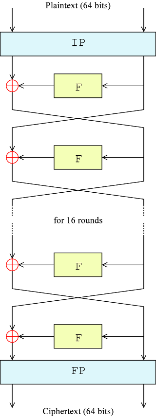
Overall structure
The algorithm's overall structure is shown in the figure below: there are 16 identical stages of processing, termed rounds. There is also an initial and final permutation, termed IP and FP, which are inverses (IP "undoes" the action of FP, and vice versa). IP and FP have no cryptographic significance, but were included in order to facilitate loading blocks in and out of mid-1970s 8-bit based hardware
Before the main rounds, the block is divided into two 32-bit halves and processed alternately; this criss-crossing is known as the Feistel scheme. The Feistel structure ensures that decryption and encryption are very similar processes—the only difference is that the subkeys are applied in the reverse order when decrypting. The rest of the algorithm is identical. This greatly simplifies implementation, particularly in hardware, as there is no need for separate encryption and decryption algorithms
The  symbol denotes the exclusive-OR (XOR) operation. The F-function scrambles half a block together with some of the key. The output from the F-function is then combined with the other half of the block, and the halves are swapped before the next round. After the final round, the halves are swapped; this is a feature of the Feistel structure which makes encryption and decryption similar processes
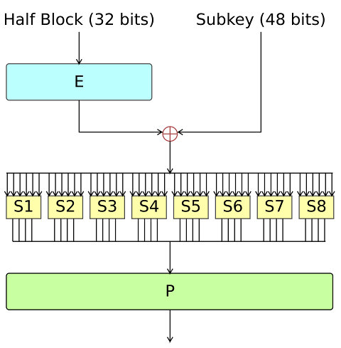
The Feistel (F) function
The F-function, depicted in the figure below, operates on half a block (32 bits) at a time and consists of four stages:
- Expansion: the 32-bit half-block is expanded to 48 bits using the expansion permutation, denoted E in the diagram, by duplicating half of the bits. The output consists of eight 6-bit (8 * 6 = 48 bits) pieces, each containing a copy of 4 corresponding input bits, plus a copy of the immediately adjacent bit from each of the input pieces to either side
- Key mixing: the result is combined with a subkey using an XOR operation. Sixteen 48-bit subkeys—one for each round—are derived from the main key using the key schedule (described below)
- Substitution: after mixing in the subkey, the block is divided into eight 6-bit pieces before processing by the S-boxes, or substitution boxes. Each of the eight S-boxes replaces its six input bits with four output bits according to a non-linear transformation, provided in the form of a lookup table. The S-boxes provide the core of the security of DES—without them, the cipher would be linear, and trivially breakable
- Permutation: finally, the 32 outputs from the S-boxes are rearranged according to a fixed permutation, the P-box. This is designed so that, after permutation, the bits from the output of each S-box in this round are spread across four different S-boxes in the next round
The alternation of substitution from the S-boxes, and permutation of bits from the P-box and E-expansion provides so-called "confusion and diffusion" respectively, a concept identified by Claude Shannon in the 1940s as a necessary condition for a secure yet practical cipher
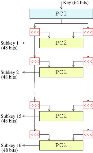
Key schedule
The figure below illustrates the key schedule for encryption—the algorithm which generates the subkeys. Initially, 56 bits of the key are selected from the initial 64 by Permuted Choice 1 (PC-1)—the remaining eight bits are either discarded or used as parity check bits. The 56 bits are then divided into two 28-bit halves; each half is thereafter treated separately. In successive rounds, both halves are rotated left by one or two bits (specified for each round), and then 48 subkey bits are selected by Permuted Choice 2 (PC-2)—24 bits from the left half, and 24 from the right. The rotations (denoted by "<<<" in the diagram) mean that a different set of bits is used in each subkey; each bit is used in approximately 14 out of the 16 subkeys
The key schedule for decryption is similar—the subkeys are in reverse order compared to encryption. Apart from that change, the process is the same as for encryption. The same 28 bits are passed to all rotation boxes
Security and cryptanalysis
Although more information has been published on the cryptanalysis of DES than any other block cipher, the most practical attack to date is still a brute-force approach. Various minor cryptanalytic properties are known, and three theoretical attacks are possible which, while having a theoretical complexity less than a brute-force attack, require an unrealistic number of known or chosen plaintexts to carry out, and are not a concern in practice
Brute-force attack
For any cipher, the most basic method of attack is brute force—trying every possible key in turn. The length of the key determines the number of possible keys, and hence the feasibility of this approach. For DES, questions were raised about the adequacy of its key size early on, even before it was adopted as a standard, and it was the small key size, rather than theoretical cryptanalysis, which dictated a need for a replacement algorithm. As a result of discussions involving external consultants including the NSA, the key size was reduced from 128 bits to 56 bits to fit on a single chip
The EFF's US$250,000 DES cracking machine contained 1,856 custom chips and could brute-force a DES key in a matter of days—the photo shows a DES Cracker circuit board fitted with several Deep Crack chips
In academia, various proposals for a DES-cracking machine were advanced. In 1977, Diffie and Hellman proposed a machine costing an estimated US$20 million which could find a DES key in a single day.[1][31] By 1993, Wiener had proposed a key-search machine costing US$1 million which would find a key within 7 hours. However, none of these early proposals were ever implemented—or, at least, no implementations were publicly acknowledged. The vulnerability of DES was practically demonstrated in the late 1990s. In 1997, RSA Security sponsored a series of contests, offering a $10,000 prize to the first team that broke a message encrypted with DES for the contest. That contest was won by the DESCHALL Project, led by Rocke Verser, Matt Curtin, and Justin Dolske, using idle cycles of thousands of computers across the Internet. The feasibility of cracking DES quickly was demonstrated in 1998 when a custom DES-cracker was built by the Electronic Frontier Foundation (EFF), a cyberspace civil rights group, at the cost of approximately US$250,000 (see EFF DES cracker). Their motivation was to show that DES was breakable in practice as well as in theory: "There are many people who will not believe a truth until they can see it with their own eyes. Showing them a physical machine that can crack DES in a few days is the only way to convince some people that they really cannot trust their security to DES." The machine brute-forced a key in a little more than 2 days' worth of searching
The next confirmed DES cracker was the COPACOBANA machine built in 2006 by teams of the Universities of Bochum and Kiel, both in Germany. Unlike the EFF machine, COPACOBANA consists of commercially available, reconfigurable integrated circuits. 120 of these field-programmable gate arrays (FPGAs) of type XILINX Spartan-3 1000 run in parallel. They are grouped in 20 DIMM modules, each containing 6 FPGAs. The use of reconfigurable hardware makes the machine applicable to other code breaking tasks as well. One of the more interesting aspects of COPACOBANA is its cost factor. One machine can be built for approximately $10,000. The cost decrease by roughly a factor of 25 over the EFF machine is an example of the continuous improvement of digital hardware—see Moore's law. Adjusting for inflation over 8 years yields an even higher improvement of about 30x. Since 2007, SciEngines GmbH, a spin-off company of the two project partners of COPACOBANA has enhanced and developed successors of COPACOBANA. In 2008 their COPACOBANA RIVYERA reduced the time to break DES to less than one day, using 128 Spartan-3 5000's. SciEngines RIVYERA held the record in brute-force breaking DES, having utilized 128 Spartan-3 5000 FPGAs. Their 256 Spartan-6 LX150 model has further lowered this time
In 2012, David Hulton and Moxie Marlinspike announced a system with 48 Xilinx Virtex-6 LX240T FPGAs, each FPGA containing 40 fully pipelined DES cores running at 400 MHz, for a total capacity of 768 gigakeys/sec. The system can exhaustively search the entire 56-bit DES key space in about 26 hours and this service is offered for a fee online
Triple DES
See https://en.wikipedia.org/wiki/Triple_DES
In cryptography, Triple DES (3DES or TDES), officially the Triple Data Encryption Algorithm (TDEA or Triple DEA), is a symmetric-key block cipher, which applies the DES cipher algorithm three times to each data block. The Data Encryption Standard’s(DES) 56-bit key is no longer considered adequate in the face of modern cryptanalytic techniques and supercomputing power. However, an adapted version of DES, Triple DES (3DES), uses the same algorithm to produce a more secure encryption
While the government and industry standards abbreviate the algorithm's name as TDES (Triple DES) and TDEA (Triple Data Encryption Algorithm),[1] RFC 1851 referred to it as 3DES from the time it first promulgated the idea, and this namesake has since come into wide use by most vendors, users, and cryptographers
Algorithm
The original DES cipher's key size of 56 bits was generally sufficient when that algorithm was designed, but the availability of increasing computational power made brute-force attacks feasible. Triple DES provides a relatively simple method of increasing the key size of DES to protect against such attacks, without the need to design a completely new block cipher algorithm
A naive approach to increase strength of a block encryption algorithm with short key length (like DES) would be to use two keys (K1, K2) instead of one, and encrypt each block twice:  . If the original key length is n bits, one would hope this scheme provides security equivalent to using key 2n bits long. Unfortunately, this approach is vulnerable to meet-in-the-middle attack: given a known plaintext pair (x, y), such that
  , one can recover the key pair (K1, K2) in
  steps, instead of
  steps one would expect from an ideally secure algorithm with 2n bits of key
Therefore, Triple DES uses a "key bundle" that comprises three DES keys, K1, K2 and K3, each of 56 bits (excluding parity bits). The encryption algorithm is:

That is, DES encrypt with K1, DES decrypt with K2, then DES encrypt with K3. Decryption is the reverse:

That is, decrypt with K3, encrypt with K2, then decrypt with K1
Each triple encryption encrypts one block of 64 bits of data
In each case the middle operation is the reverse of the first and last. This improves the strength of the algorithm when using keying option 2 and provides backward compatibility with DES with keying option 3
Keying options
The standards define three keying options:
- Keying option 1
- All three keys are independent. Sometimes known as 3TDEA or triple-length keys. This is the strongest, with 3 × 56 = 168 independent key bits. It is still vulnerable to meet-in-the-middle attack, but the attack requires

- All three keys are independent. Sometimes known as 3TDEA or triple-length keys. This is the strongest, with 3 × 56 = 168 independent key bits. It is still vulnerable to meet-in-the-middle attack, but the attack requires
- Keying option 2
- K1 and K2 are independent, and K3 = K1. Sometimes known as 2TDEA or double-length keys. This provides a shorter key length of 112 bits and a reasonable compromise between DES and Kehttps://en.wikipedia.org/wiki/Triple_DESying option 1, with the same caveat as above. This is an improvement over "double DES" which only requires 256 steps to attack. NIST has deprecated this option
- Keying option 3
- All three keys are identical, i.e. K1 = K2 = K3. This is backward compatible with DES, since two operations cancel out. ISO/IEC 18033-3 never allowed this option, and NIST no longer allows K1 = K2 or K2 = K3
Each DES key is 8 odd-parity bytes, with 56 bits of key and 8 bits of error-detection. A key bundle requires 24 bytes for option 1, 16 for option 2, or 8 for option 3
NIST (and the current TCG specifications version 2.0 of approved algorithms for Trusted Platform Module) also disallows using any one of the 64 following 64-bit values in any keys (note that 32 of them are the binary complement of the 32 others; and that 32 of these keys are also the reverse permutation of bytes of the 32 others), listed here in hexadecimal (in each byte, the least significant bit is a odd-parity generated bit, it is discarded when forming the effective 56-bit keys):
With these restrictions on allowed keys, Triple DES has been reapproved with keying options 1 and 2 only. Generally the three keys are generated by taking 24 bytes from a strong random generator and only keying option 1 should be used (option 2 needs only 16 random bytes, but strong random generators are hard to assert and it's considered best practice to use only option 1)
Usage
The electronic payment industry uses Triple DES and continues to develop and promulgate standards based upon it, such as EMV
Earlier versions of Microsoft OneNote, Microsoft Outlook 2007 and Microsoft System Center Configuration Manager 2012 use Triple DES to password-protect user content and system data. However, in December 2018, Microsoft announced the retirement of 3DES throughout their Office 365 service
Firefox and Mozilla Thunderbird use Triple DES in CBC mode to encrypt website authentication login credentials when using a master password
The Advanced Encryption Standard (AES)
Also known by its original name Rijndael is a specification for the encryption of electronic data established by the U.S. National Institute of Standards and Technology (NIST) in 2001. AES is a subset of the Rijndael block cipher developed by two Belgian cryptographers, Vincent Rijmen and Joan Daemen, who submitted a proposal to NIST during the AES selection process. Rijndael is a family of ciphers with different key and block sizes
For AES, NIST selected three members of the Rijndael family, each with a block size of 128 bits, but three different key lengths: 128, 192 and 256 bits
AES has been adopted by the U.S. government and is now used worldwide. It supersedes the Data Encryption Standard (DES), which was published in 1977. The algorithm described by AES is a symmetric-key algorithm, meaning the same key is used for both encrypting and decrypting the data
In the United States, AES was announced by the NIST as U.S. FIPS PUB 197 (FIPS 197) on November 26,
- This announcement followed a five-year standardization process in which fifteen competing designs were presented and evaluated, before the Rijndael cipher was selected as the most suitable (see Advanced Encryption Standard process for more details)
AES became effective as a federal government standard on May 26, 2002, after approval by the Secretary of Commerce. AES is included in the ISO/IEC 18033-3 standard. AES is available in many different encryption packages, and is the first (and only) publicly accessible cipher approved by the National Security Agency (NSA) for top secret information when used in an NSA approved cryptographic module (see Security of AES, below)
Description of the ciphers
AES is based on a design principle known as a substitution–permutation network, and is efficient in both software and hardware. Unlike its predecessor DES, AES does not use a Feistel network. AES is a variant of Rijndael which has a fixed block size of 128 bits, and a key size of 128, 192, or 256 bits. By contrast, Rijndael per se is specified with block and key sizes that may be any multiple of 32 bits, with a minimum of 128 and a maximum of 256 bits
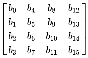
AES operates on a 4 × 4 column-major order array of bytes, termed the state. Most AES calculations are done in a particular finite field
For instance, if there are 16 bytes,  these bytes are represented as this two-dimensional array:
The key size used for an AES cipher specifies the number of transformation rounds that convert the input, called the plaintext, into the final output, called the ciphertext. The number of rounds are as follows:
- 10 rounds for 128-bit keys
- 12 rounds for 192-bit keys
- 14 rounds for 256-bit keys
Each round consists of several processing steps, including one that depends on the encryption key itself. A set of reverse rounds are applied to transform ciphertext back into the original plaintext using the same encryption key
High-level description of the algorithm
- KeyExpansion—round keys are derived from the cipher key using Rijndael's key schedule. AES requires a separate 128-bit round key block for each round plus one more
- Initial round key addition:
- AddRoundKey—each byte of the state is combined with a block of the round key using bitwise xor
- 9, 11 or 13 rounds:
- SubBytes—a non-linear substitution step where each byte is replaced with another according to a lookup table
- ShiftRows—a transposition step where the last three rows of the state are shifted cyclically a certain number of steps
- MixColumns—a linear mixing operation which operates on the columns of the state, combining the four bytes in each column.
- AddRoundKey
- Final round (making 10, 12 or 14 rounds in total):
- SubBytes
- ShiftRows
- AddRoundKey
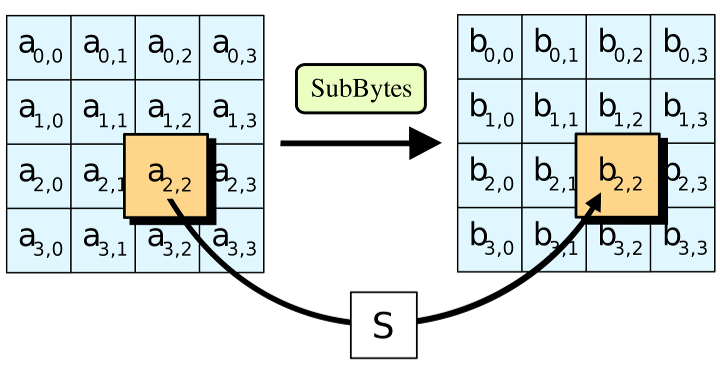
The SubBytes step
In the SubBytes step, each byte  in the state array is replaced with a SubByte
  using an 8-bit substitution box. This operation provides the non-linearity in the cipher. The S-box used is derived from the multiplicative inverse over GF(28), known to have good non-linearity properties. To avoid attacks based on simple algebraic properties, the S-box is constructed by combining the inverse function with an invertible affine transformation. The S-box is also chosen to avoid any fixed points (and so is a derangement), i.e.,
  , and also any opposite fixed points, i.e.,
  . While performing the decryption, the InvSubBytes step (the inverse of SubBytes) is used, which requires first taking the inverse of the affine transformation and then finding the multiplicative inverse
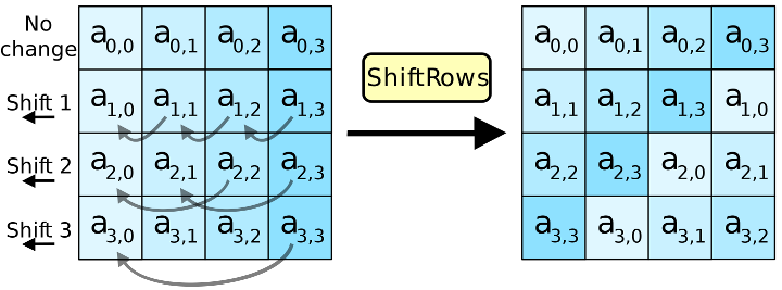
The ShiftRows step
In the ShiftRows step, bytes in each row of the state are shifted cyclically to the left. The number of places each byte is shifted differs for each row. The ShiftRows step operates on the rows of the state; it cyclically shifts the bytes in each row by a certain offset. For AES, the first row is left unchanged. Each byte of the second row is shifted one to the left. Similarly, the third and fourth rows are shifted by offsets of two and three respectively. In this way, each column of the output state of the ShiftRows step is composed of bytes from each column of the input state. The importance of this step is to avoid the columns being encrypted independently, in which case AES degenerates into four independent block ciphers
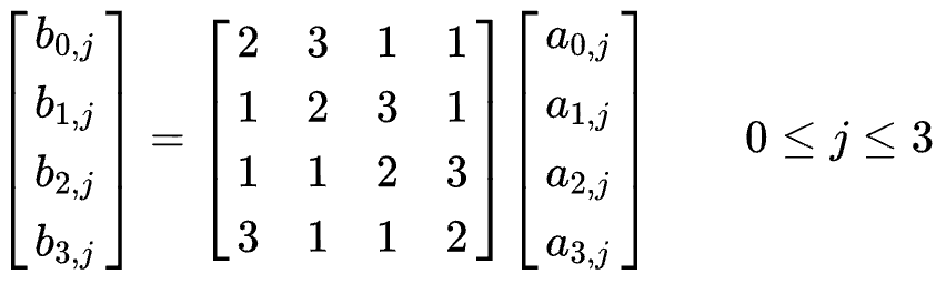
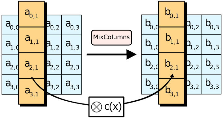
The MixColumns step
In the MixColumns step, each column of the state is multiplied with a fixed polynomial 
In the MixColumns step, the four bytes of each column of the state are combined using an invertible linear transformation. The MixColumns function takes four bytes as input and outputs four bytes, where each input byte affects all four output bytes. Together with ShiftRows, MixColumns provides diffusion in the cipher
During this operation, each column is transformed using a fixed matrix (matrix left-multiplied by column gives new value of column in the state):
Matrix multiplication is composed of multiplication and addition of the entries. Entries are 8-bit bytes treated as coefficients of polynomial of order  . Addition is simply XOR. Multiplication is modulo irreducible polynomial
  . If processed bit by bit, then, after shifting, a conditional XOR with
  should be performed if the shifted value is larger than
  (overflow must be corrected by subtraction of generating polynomial). These are special cases of the usual multiplication in
In more general sense, each column is treated as a polynomial over and is then multiplied modulo  with a fixed polynomial
  The coefficients are displayed in their hexadecimal equivalent of the binary representation of bit polynomials from
 ![$ GF(2)[x] $](form_26.png) . The MixColumns step can also be viewed as a multiplication by the shown particular MDS matrix in the finite field . This process is described further in the article Rijndael MixColumns
. The MixColumns step can also be viewed as a multiplication by the shown particular MDS matrix in the finite field . This process is described further in the article Rijndael MixColumns
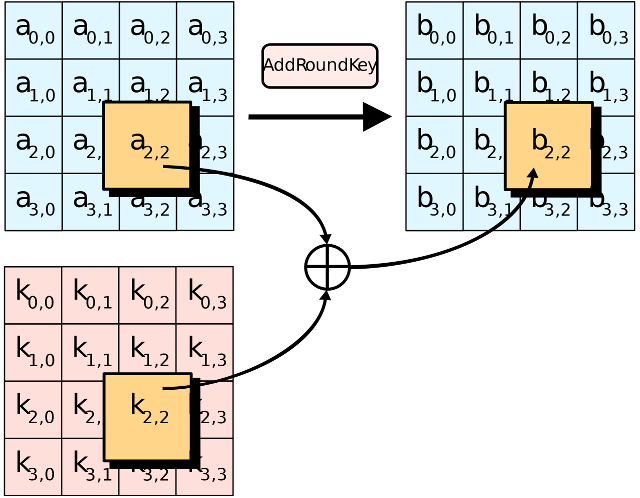
The AddRoundKey step
In the AddRoundKey step, the subkey is combined with the state. For each round, a subkey is derived from the main key using Rijndael's key schedule; each subkey is the same size as the state. The subkey is added by combining each byte of the state with the corresponding byte of the subkey using bitwise XOR
Optimization of the cipher
On systems with 32-bit or larger words, it is possible to speed up execution of this cipher by combining the SubBytes and ShiftRows steps with the MixColumns step by transforming them into a sequence of table lookups. This requires four 256-entry 32-bit tables (together occupying 4096 bytes). A round can then be performed with 16 table lookup operations and 12 32-bit exclusive-or operations, followed by four 32-bit exclusive-or operations in the AddRoundKey step. Alternatively, the table lookup operation can be performed with a single 256-entry 32-bit table (occupying 1024 bytes) followed by circular rotation operations
Using a byte-oriented approach, it is possible to combine the SubBytes, ShiftRows, and MixColumns steps into a single round operation
Security
Until May 2009, the only successful published attacks against the full AES were side-channel attacks on some specific implementations. The National Security Agency (NSA) reviewed all the AES finalists, including Rijndael, and stated that all of them were secure enough for U.S. Government non-classified data. In June 2003, the U.S. Government announced that AES could be used to protect classified information:
The design and strength of all key lengths of the AES algorithm (i.e., 128, 192 and 256) are sufficient to protect classified information up to the SECRET level. TOP SECRET information will require use of either the 192 or 256 key lengths. The implementation of AES in products intended to protect national security systems and/or information must be reviewed and certified by NSA prior to their acquisition and use
AES has 10 rounds for 128-bit keys, 12 rounds for 192-bit keys, and 14 rounds for 256-bit keys
By 2006, the best known attacks were on 7 rounds for 128-bit keys, 8 rounds for 192-bit keys, and 9 rounds for 256-bit keys
Performance
High speed and low RAM requirements were criteria of the AES selection process. As the chosen algorithm, AES performed well on a wide variety of hardware, from 8-bit smart cards to high-performance computers
On a Pentium Pro, AES encryption requires 18 clock cycles per byte, equivalent to a throughput of about 11 Mbit/s for a 200 MHz processor. On a 1.7 GHz Pentium M throughput is about 60 Mbit/s
On Intel Core i3/i5/i7 and AMD Ryzen CPUs supporting AES-NI instruction set extensions, throughput can be multiple GB/s (even over 10 GB/s)
Serpent Block Cipher
Serpent is a symmetric key block cipher that was a finalist in the Advanced Encryption Standard (AES) contest, where it was ranked second to Rijndael. Serpent was designed by Ross Anderson, Eli Biham, and Lars Knudsen
Like other AES submissions, Serpent has a block size of 128 bits and supports a key size of 128, 192 or 256 bits. The cipher is a 32-round substitution–permutation network operating on a block of four 32-bit words. Each round applies one of eight 4-bit to 4-bit S-boxes 32 times in parallel. Serpent was designed so that all operations can be executed in parallel, using 32 bit slices. This maximizes parallelism, but also allows use of the extensive cryptanalysis work performed on DES
Serpent took a conservative approach to security, opting for a large security margin: the designers deemed 16 rounds to be sufficient against known types of attack, but specified 32 rounds as insurance against future discoveries in cryptanalysis. The official NIST report on AES competition classified Serpent as having a high security margin along with MARS and Twofish, in contrast to the adequate security margin of RC6 and Rijndael (currently AES). In final voting, Serpent had the fewest negative votes among the finalists, but scored second place overall because Rijndael had substantially more positive votes, the deciding factor being that Rijndael allowed for a far more efficient software implementation
The Serpent cipher algorithm is in the public domain and has not been patented. The reference code is public domain software and the optimized code is under GPL. There are no restrictions or encumbrances whatsoever regarding its use. As a result, anyone is free to incorporate Serpent in their software (or hardware implementations) without paying license fees
Rijndael vs. Serpent
Rijndael is a substitution-linear transformation network with ten, twelve, or fourteen rounds, depending on the key size, and with block sizes of 128 bits, 192 bits, or 256 bits, independently specified. Serpent is a substitution–permutation network which has thirty-two rounds, plus an initial and a final permutation to simplify an optimized implementation. The round function in Rijndael consists of three parts: a nonlinear layer, a linear mixing layer, and a key-mixing XOR layer. The round function in Serpent consists of key-mixing XOR, thirty-two parallel applications of the same 4×4 S-box, and a linear transformation, except in the last round, wherein another key-mixing XOR replaces the linear transformation. The nonlinear layer in Rijndael uses an 8×8 S-box whereas Serpent uses eight different 4×4 S-boxes. The 32 rounds means that Serpent has a higher security margin than Rijndael; however, Rijndael with 10 rounds is faster and easier to implement for small blocks. Hence, Rijndael was selected as the winner in the AES competition
Serpent-0 vs. Serpent-1
The original Serpent, Serpent-0, was presented at the 5th workshop on Fast Software Encryption, but a somewhat tweaked version, Serpent-1, was submitted to the AES competition. The AES submission paper discuss the changes, which include key scheduling differences
Security
The XSL attack, if effective, would weaken Serpent (though not as much as it would weaken Rijndael, which became AES). However, many cryptanalysts believe that once implementation considerations are taken into account the XSL attack would be more expensive than a brute force attack
In 2000, a paper by Kohno et al. presents a meet-in-the-middle attack against 6 of 32 rounds of Serpent and an amplified boomerang attack against 9 of 32 rounds in Serpent
A 2001 attack by Eli Biham, Orr Dunkelman and Nathan Keller presents a linear cryptanalysis attack that breaks 10 of 32 rounds of Serpent-128 with 2118 known plaintexts and 289 time, and 11 rounds of Serpent-192/256 with 2118 known plaintexts and 2187 time
A 2009 paper has noticed that the nonlinear order of Serpent S-boxes were not 3 as was claimed by the designers
A 2011 attack by Hongjun Wu, Huaxiong Wang and Phuong Ha Nguyen, also using linear cryptanalysis, breaks 11 rounds of Serpent-128 with 2116 known plaintexts, 2107.5 time and 2104 memory
The same paper also describes two attacks which break 12 rounds of Serpent-256. The first requires 2118 known plaintexts, 2228.8 time and 2228 memory. The other attack requires 2116 known plaintexts and 2121 memory but also requires 2237.5 time
ARIA Block Cipher (Korea)
ARIA is a general-purpose block cipher algorithm developed by Korean cryptographers in 2003. It is an iterated block cipher with 128-, 192-, and 256-bit keys and encrypts 128-bit blocks in 12, 14, and 16 rounds, depending on the key size. It is secure and suitable for most software and hardware implementations on 32-bit and 8-bit processors. It was established as a Korean standard block cipher algorithm in 2004 [ARIAKS] and has been widely used in Korea, especially for government-to-public services. It was included in PKCS #11 in 2007 [ARIAPKCS]. The algorithm specification and object identifiers are described in [RFC5794].
ARIA-CTR
Section 4.1.1 of [RFC3711] defines AES-128 counter mode encryption, which it refers to as "AES_CM". Section 2 of [RFC6188] defines "AES_192_CM" and "AES_256_CM" in SRTP. ARIA counter modes are defined in the same manner except that each invocation of AES is replaced by that of ARIA [RFC5794], and are denoted by ARIA_128_CTR, ARIA_192_CTR and ARIA_256_CTR respectively, according to the key lengths. The plaintext inputs to the block cipher are formed as in AES-CTR(AES_CM, AES_192_CM, AES_256_CM) and the block cipher outputs are processed as in AES-CTR. Note that, ARIA-CTR MUST be used only in conjunction with an authentication transform.
ARIA-GCM
GCM (Galois Counter Mode) [GCM][RFC5116] is an AEAD (Authenticated Encryption with Associated Data) block cipher mode. A detailed description of ARIA-GCM is defined similarly as AES-GCM found in [RFC5116][RFC5282].
SM4 Block Cipher (China)
See sm4_encryption_spec 15 May 2008 Version 1.03
SMS4 is a Chinese block cipher standard, mandated for use in protecting wireless networks and issued in January 2006. The input, output, and key of SMS4 are each 128 bits. The algorithm has 32 rounds, each of which modifies one of the four 32-bit words that make up the block by xoring it with a keyed function of the other three words. Encryption and decryption have the same structure except that the round key schedule for decryption is the reverse of the round key schedule for encryption
1. Terminology (Definitions)
1.1 Zi and ZiJie (Word and Byte)
 is the set of e-bit vectors. Specifically, the elements of
  are called
  (32-bit words), and the elements of
  are called
  (8-bit characters, or bytes)
1.2 S box
The S (substitution) box takes in 8 bits and outputs 8 bits. It is written Sbox(.)
1.3 Fundamental Operations
The two fundamental operations used by this algorithm are:
- the bitwise XOR of two 32-bit vectors
 i the circular shift of a 32-bit word, with i bits shifted left
1.4 Input and output blocks and key
The 128-bit input block consists of four 32-bit words 
The round key schedule, derived from the encryption key, is represented by  where each
  is 32 bits long
The 128-bit output block consists of four 32-bit words 
For decryption, the round key schedule is represented by  or
or

2. The round function F
This algorithm uses a nonlinear substitution structure, encrypting 32 bits at a time. This is called a one-round exchange. To illustrate, consider a one-round-substitution:
Let the 128-bit input block be the four 32-bit elements
 , with
  , then F is given by
2.1 Mixer-substitution T
T is a substitution that generates 32 bits from 32 bits  . This substitution is a reversible process. It consists of a non-linear substitution,
  , and a linear substitution L, i.e.,
2.1.1 Non-linear substitution 
applies 4 S-boxes in parallel Let a 32-bit input word be  , where each ai is an 8-bit character Let the 32-bit output word be
  , given by
2.1.2 Linear substitution L
 , the 32-bit output word of the non-linear substitution will be the input word of the linear substitution L. Let
  be the 32-bit output word generated by L. Then

2.2 S box
All Sbox numbers are in hexadecimal notation
| 0 | 1 | 2 | 3 | 4 | 5 | 6 | 7 | 8 | 9 | 10 | 11 | 12 | 13 | 14 | 15 |
|---|---|---|---|---|---|---|---|---|---|---|---|---|---|---|---|
| d6 | 90 | e9 | fe | cc | e1 | 3d | b7 | 16 | b6 | 14 | c2 | 28 | fb | 2c | 05 |
| 2b | 67 | 9a | 76 | 2a | be | 04 | c3 | aa | 44 | 13 | 26 | 49 | 86 | 06 | 99 |
| 9c | 42 | 50 | f4 | 91 | ef | 98 | 7a | 33 | 54 | 0b | 43 | ed | cf | ac | 62 |
| e4 | b3 | 1c | a9 | c9 | 08 | e8 | 95 | 80 | df | 94 | fa | 75 | 8f | 3f | a6 |
| 47 | 07 | a7 | fc | f3 | 73 | 17 | ba | 83 | 59 | 3c | 19 | e6 | 85 | 4f | a8 |
| 68 | 6b | 81 | b2 | 71 | 64 | da | 8b | f8 | eb | 0f | 4b | 70 | 56 | 9d | 35 |
| 1e | 24 | 0e | 5e | 63 | 58 | d1 | a2 | 25 | 22 | 7c | 3b | 01 | 21 | 78 | 87 |
| d4 | 00 | 46 | 57 | 9f | d3 | 27 | 52 | 4c | 36 | 02 | e7 | a0 | c4 | c8 | 9e |
| ea | bf | 8a | d2 | 40 | c7 | 38 | b5 | a3 | f7 | f2 | ce | f9 | 61 | 15 | a1 |
| e0 | ae | 5d | a4 | 9b | 34 | 1a | 55 | ad | 93 | 32 | 30 | f5 | 8c | b1 | e3 |
| 1d | f6 | e2 | 2e | 82 | 66 | ca | 60 | c0 | 29 | 23 | ab | 0d | 53 | 4e | 6f |
| d5 | db | 37 | 45 | de | fd | 8e | 2f | 03 | ff | 6a | 72 | 6d | 6c | 5b | 51 |
| 8d | 1b | af | 92 | bb | dd | bc | 7f | 11 | d9 | 5c | 41 | 1f | 10 | 5a | d8 |
| 0a | c1 | 31 | 88 | a5 | cd | 7b | bd | 2d | 74 | d0 | 12 | b8 | e5 | b4 | b0 |
| 89 | 69 | 97 | 4a | 0c | 96 | 77 | 7e | 65 | b9 | f1 | 09 | c5 | 6e | c6 | 84 |
| 18 | f0 | 7d | ec | 3a | dc | 4d | 20 | 79 | ee | 5f | 3e | d7 | cb | 39 | 48 |

For example, if the input to the Sbox is 'ef', then go to e-th row and f-th column, to find 
3. Encryption and decryption
Let the reverse substitution  be:
be:

Let the plaintext input be , the ciphertext output be 
 , and the encrypting key be
Then encryption proceeds as follows:
 where
where 

This algorithm's encryption and decryption methods have the same structure, except the order in which the round keys are used is reversed
The key order for encryption is:  . The key order for decryption is:

4. Key expansion when encrypting
The  round key used for encrypting in this algorithm is derived from the encryption key MK.
Let 

 ;
;
the derivation proceeds as follows:
First,

Then for i = 0,1,2,...,31:

Notes:
- T&prime substitution uses the same T as in encryption, except the linear substitution L is changed to L&prime: L&prime
 ;
; - The system parameter
 given in hexadecimal notation is

- The constant parameter
 is calculated as follows:
Let  be the j-th byte of
  , i.e.,
The 32 constants  are represented in hexadecimal as tabulated below:
| 0 | 1 | 2 | 3 |
|---|---|---|---|
| 00070e15 | 1c232a31 | 383f464d | 545b6269 |
| 70777e85 | 8c939aa1 | a8afb6bd | c4cbd2d9 |
| e0e7eef5 | fc030a11 | 181f262d | 343b4249 |
| 50575e65 | 6c737a81 | 888f969d | a4abb2b9 |
| c0c7ced5 | dce3eaf1 | f8ff060d | 141b2229 |
| 30373e45 | 4c535a61 | 686f767d | 848b9299 |
| a0a7aeb5 | bcc3cad1 | d8dfe6ed | f4fb0209 |
| 10171e25 | 2c333a41 | 484f565d | 646b7279 |

Camellia Block Cipher (Japan)

See https://en.wikipedia.org/wiki/Camellia_(cipher)
See https://info.isl.ntt.co.jp/crypt/eng/camellia/dl/01espec.pdf
In cryptography, Camellia is a symmetric key block cipher with a block size of 128 bits and key sizes of 128, 192 and 256 bits. It was jointly developed by Mitsubishi Electric and NTT of Japan. The cipher has been approved for use by the ISO/IEC, the European Union's NESSIE project and the Japanese CRYPTREC project. The cipher has security levels and processing abilities comparable to the Advanced Encryption Standard
The cipher was designed to be suitable for both software and hardware implementations, from low-cost smart cards to high-speed network systems. It is part of the Transport Layer Security (TLS) cryptographic protocol designed to provide communications security over a computer network such as the Internet
The cipher was named for the flower Camellia japonica, which is known for being long-lived as well as because the cipher was developed in Japan
Design
Camellia is a Feistel cipher with either 18 rounds (when using 128-bit keys) or 24 rounds (when using 192- or 256-bit keys). Every six rounds, a logical transformation layer is applied: the so-called "FL-function" or its inverse. Camellia uses four 8×8-bit S-boxes with input and output affine transformations and logical operations. The cipher also uses input and output key whitening. The diffusion layer uses a linear transformation based on a matrix with a branch number of 5
Security analysis
Camellia is considered a modern, safe cipher. Even using the smaller key size option (128 bits), it's considered infeasible to break it by brute-force attack on the keys with current technology. There are no known successful attacks that weaken the cipher considerably. The cipher has been approved for use by the ISO/IEC, the European Union's NESSIE project and the Japanese CRYPTREC project. The Japanese cipher has security levels and processing abilities comparable to the AES/Rijndael cipher
Camellia is a block cipher which can be completely defined by minimal systems of multivariate polynomials:
- The Camellia (as well as AES) S-boxes can be described by a system of 23 quadratic equations in 80 terms
- The key schedule can be described by 1,120 equations in 768 variables using 3,328 linear and quadratic terms
- The entire block cipher can be described by 5,104 equations in 2,816 variables using 14,592 linear and quadratic terms
- In total, 6,224 equations in 3,584 variables using 17,920 linear and quadratic terms are required
- The number of free terms is 11,696, which is approximately the same number as for AES
Theoretically, such properties might make it possible to break Camellia (and AES) using an algebraic attack, such as extended sparse linearisation, in the future, provided that the attack becomes feasible
SEED Block Cipher (Korea)
SEED is a block cipher developed by the Korea Internet & Security Agency (KISA). It is used broadly throughout South Korean industry, but seldom found elsewhere. It gained popularity in Korea because 40-bit encryption was not considered strong enough, so the Korea Information Security Agency developed its own standard. However, this decision has historically limited the competition of web browsers in Korea, as no major SSL libraries or web browsers supported the SEED algorithm, requiring users to use an ActiveX control in Internet Explorer for secure web sites
On April 1, 2015 the Ministry of Science, ICT and Future Planning (MSIP) announced its plan to remove the ActiveX dependency from at least 90 percent of the country's top 100 websites by 2017. Instead, HTML5-based technologies will be employed as they operate on many platforms, including mobile devices. Starting with the private sector, the ministry plans to expand this further to ultimately remove this dependency from public websites as well
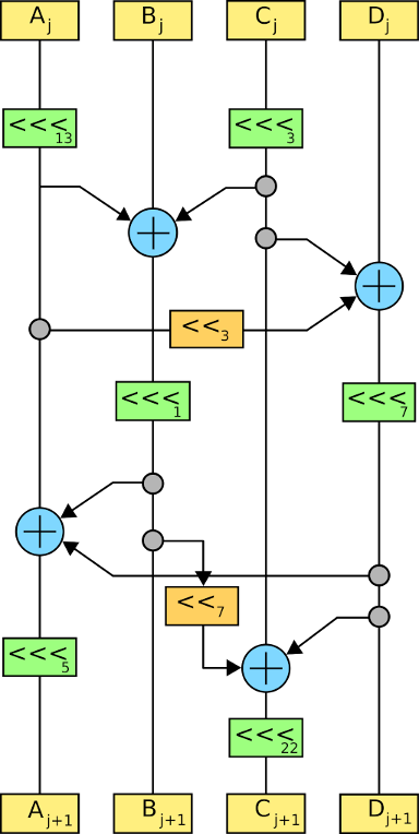
Design
SEED is a 16-round Feistel network with 128-bit blocks and a 128-bit key. It uses two 8 × 8 S-boxes which, like those of SAFER, are derived from discrete exponentiation (in this case, x247 and x251 – plus some "incompatible operations"). It also has some resemblance to MISTY1 in the recursiveness of its structure: the 128-bit full cipher is a Feistel network with an F-function operating on 64-bit halves, while the F-function itself is a Feistel network composed of a G-function operating on 32-bit halves. However the recursion does not extend further because the G-function is not a Feistel network. In the G-function, the 32-bit word is considered as four 8-bit bytes, each of which is passed through one or the other of the S-boxes, then combined in a moderately complex set of boolean functions such that each output bit depends on 3 of the 4 input bytes
SEED has a fairly complex key schedule, generating its thirty-two 32-bit subkeys through application of its G-function on a series of rotations of the raw key, combined with round constants derived (as in TEA) from the Golden ratio
ZUC Encrytpion Algorithm (128-EEA3 and 128-EIA3)
- See also
- Specification of the 3GPP Confidentiality and Integrity Algorithms 128-EEA3 and 128-EIA3 Document 2: ZUC Specification
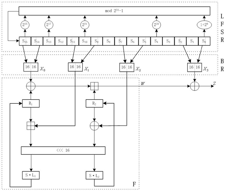
General structure of the algorithm
ZUC has three logical layers, see the figure below. The top layer is a linear feedback shift register (LFSR) of 16 stages, the middle layer is for bit-reorganization ( BR), and the bottom layer is a nonlinear function F
The linear feedback shift register (LFSR)
The linear feedback shift register (LFSR) has 16 of 31-bit cells  . Each cell
  is restricted to take values from the following set
  . The LFSR has 2 modes of operations: the initialization mode and the working mode
In the initialization mode, the LFSR receives a 31-bit input word u, which is obtained by removing the rightmost bit from the 32-bit output W of the nonlinear function F, i.e., u=W>>1. More specifically, the initialization mode works as follows:
LFSRWithInitialisationMode(u) {
 mod
mod 
 mod
mod  , then set

}
In the working mode, the LFSR does not receive any input, and it works as follows:
LFSRWithWorkMode() {
 mod
mod - , then set

}
Informative note: Since the multiplication of a 31-bit string s by  over
over  can be implemented by a cyclic shift of s to the left by i bits, only addition modulo
  is needed in step 1 of the above functions. More precisely, step 1 of the function LFSRWithInitialisationMode can be implemented by
 mod
mod
and the same implementation is needed for step 1 of the function LFSRWithWorkMode
Informative note: For two elements  over , the computation of
  mod can be done by
(1) compute v=a+b and
(2) if the carry bit is 1, then set v=v+1
Alternatively (and better if the implementation should resist possible timing attacks):
(1) compute w=a+b, where w is a 32-bit value; and
(2) set v = (least significant 31 bits of w) + (most significant bit of w)
The bit-reorganization
The middle layer of the algorithm is the bit-reorganization. It extracts 128 bits from the cells of the LFSR and forms 4 of 32-bit words, where the first three words will be used by the nonlinear function F in the bottom layer, and the last word will be involved in producing the keystream
Let  be 8 cells of LFSR as in section 3.2. Then the bitreorganization forms 4 of 32-bit words
  from the above cells as follows:
Bitreorganization() {


}
Note: The  are 31-bit integers, so
  means bits 30...15 and not 31...16 of
The nonlinear function F
The nonlinear function F has 2 of 32-bit memory cells  and
and  . Let the inputs to F be
  and
and  , which come from the outputs of the bit-reorganization (see section 3.3), then the function F outputs a 32-bit word W. The detailed process of F is as follows:
F (  ) {
) {


}
where S is a 32×32 S-box, see section 3.4.1,  and
and  are linear transforms as defined in section 3.4.2
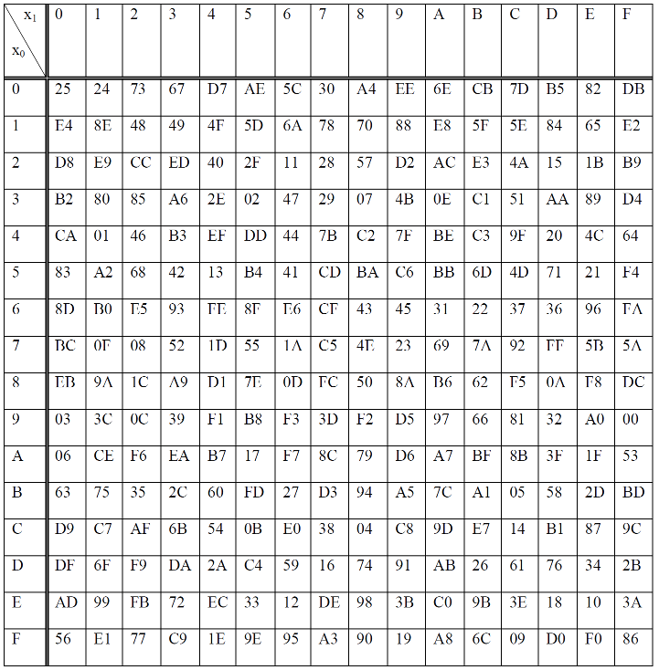
The S-box S
The 32×32 S-box S is composed of 4 juxtaposed 8×8 S-boxes, i.e., S=(  ), where
  ,
,  . The definitions of
  and
and  can be found in table 3.1 and table 3.2 respectively
Let x be an 8-bit input to (or ). Write x into two hexadecimal digits as  , then the entry at the intersection of the h-th row and the l-th column in table 3.1 (or table 3.2) is the output of (or )

The linear transforms L1 and L2
Both L1 and L2 are linear transforms from 32-bit words to 32-bit words, and are defined as follows:


Key loading
The key loading procedure will expand the initial key and the initial vector into 16 of 31-bit integers as the initial state of the LFSR. Let the 128-bit initial key k and the 128-bit initial vector iv be

and

respectively, where  and
and  , are all bytes. Then k and iv are loaded to the cells
  of LFSR as follows:
- Let D be a 240-bit long constant string composed of 16 substrings of 15 bits:

where


The execution of ZUC
The execution of ZUC has two stages: the initialization stage and the working stage
The initialization stage
During the initialization stage, the algorithm calls the key loading procedure (see section 3.5) to load the 128-bit initial key k and the 128-bit initial vector iv into the LFSR, and set the 32bit memory cells R1 and R2 to be all 0. Then the cipher runs the following operations 32 times:
- Bitreorganization();
- w=F( );
- LFSRWithInitialisationMode(w >> 1)
The working stage
After the initialization stage, the algorithm moves into the working stage. At the working stage, the algorithm executes the following operations once, and discards the output W of F:
- Bitreorganization();
- F( );
- LFSRWithWorkMode()
Then the algorithm goes into the stage of producing keystream, i.e., for each iteration, the following operations are executed once, and a 32-bit word Z is produced as an output:
- Bitreorganization();
- Z=F(
 ;
; - LFSRWithWorkMode()
Snow3g Stream Cipher (UEA2 and UIA2)
- See also
- Specification of the 3GPP Confidentiality and Integrity Algorithms UEA2 and UIA2 Document 2: SNOW 3G Specification
SNOW 3G is a word-oriented stream cipher that generates a sequence of 32-bit words under the control of a 128-bit key and a 128-bit initialisation variable. These words can be used to mask the plaintext. First a key initialisation is performed, i.e. the cipher is clocked without producing output, see 4.1. Then with every clock tick it produces a 32-bit word of output
Functions used in different Components of SNOW 3G
MULx maps 16 bits to 8 bits. Let V and c be 8-bit input values. Then MULx is defined:
If the leftmost (i.e. the most significant) bit of V equals 1, then

MULxPOW maps 16 bits and an positive integer i to 8 bit. Let V and c be 8-bit input values, then MULxPOW(V, i, c) is recursively defined:
If i equals 0, then  , else
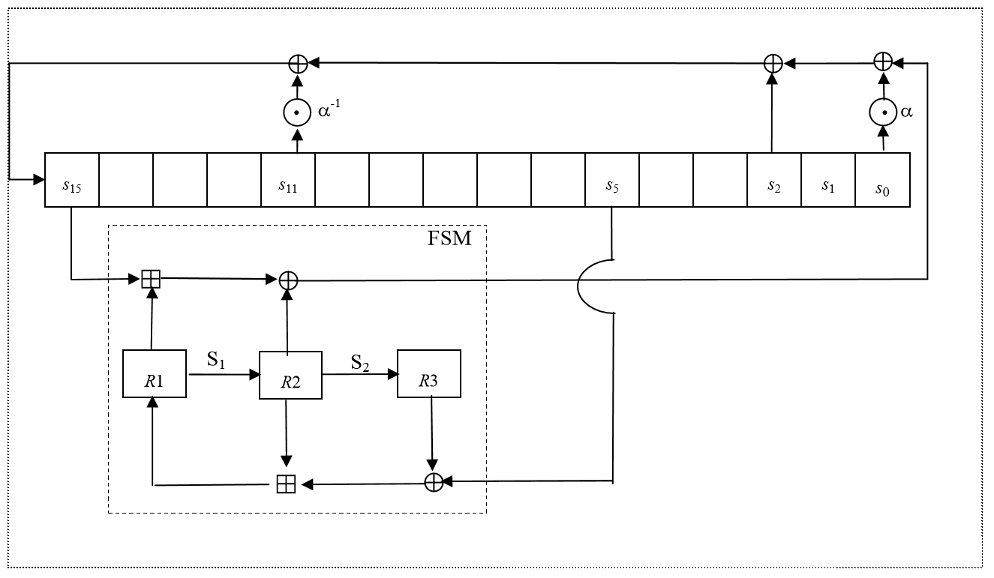
Linear Feedback Shift Register (LFSR)
The Linear Feedback Shift Register (LFSR) consists of sixteen stages  each holding 32 bits
Finite State Machine (FSM)
The Finite State Machine (FSM) has three 32-bit registers R1, R2 and R3. The S-boxes S1 and S2 are used to update the registers R2 and R3
The 32x32-bit S-Box S1
The S-Box maps a 32-bit input to a 32-bit output. Let  the 32-bit input with
  the most and
  the least significant byte
Let  with
with  the most and
  the least significant byte. We use the 8 to 8 bit Rijndael S-Box
  defined in 5.1
Then  are defined as


The 32x32-bit S-Box S2
The S-Box  maps a 32-bit input to a 32-bit output. Let the 32-bit input with the most and
  the least significant byte. Let
  with
with  the most and
  the least significant byte. We use the 8 to 8 bit S-Box
  defined in 5.2
Then are defined as


The Clocking Operations
Clocking the LFSR
The clocking of the LFSR has two different modes of operation, the Initialisation Mode 3.4.4 and the Keystream Mode 3.4.5. In both modes the functions  and
and  are used which are defined in 3.4.2 resp. 3.4.3
The function
The function maps 8 bits to 32 bits. Let c be the 8-bit input, then is defined as

The function
The function maps 8 bits to 32 bits. Let c be the 8-bit input, then is defined as

Initialisation Mode
In the Initialisation Mode the LFSR receives a 32-bit input word F, which is the output of the FSM
Let  with
with  being the most and
  being the least significant byte of
  .
.
Let  with
with  being the most and
  being the least significant byte of
Compute the intermediate value v as

Set


Keystream Mode
In the Keystream Mode the LFSR does not receive any input
Let with being the most and being the least significant byte of
Let  with being the most and being the least significant byte of
Compute the intermediate value v as
v = 
Set

Clocking the FSM
The FSM has two input words  and
and  from the LFSR. It produces a 32-bit output word F:

Then the registers are updated. Compute the intermediate value r as

Set


Operation of SNOW 3G
Initialisation
SNOW 3G is initialized with a 128-bit key consisting of four 32-bit words  and an 128-bit initialisation variable consisting of four 32-bit words
  as follows
Let 1 be the all-ones word (0xffffffff)


The FSM is initialised with 
Then the cipher runs in a special mode without producing output:
repeat 32-times {
STEP 1: The FSM is clocked (see 3.4.6) producing the 32-bit word F
STEP 2: Then the LFSR is clocked in Initialisation Mode (see 3.4.4) consuming F
}
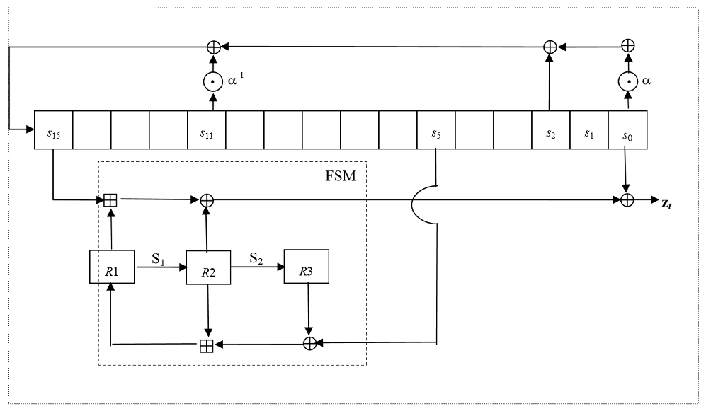
Generation of Keystream
First the FSM is clocked once, see 3.4.6. The output word of the FSM is discarded. Then the LFSR is clocked once in Keystream Mode, see 3.4.4
After that n 32-bit words of keystream are produced:
for t = 1 to n {
STEP 1: The FSM is clocked (see 3.4.6) and produces a 32-bit output word F
STEP 2: The next keystream word is computed as 
STEP 3: Then the LFSR is clocked in Keystream Mode, see 3.4.4
}
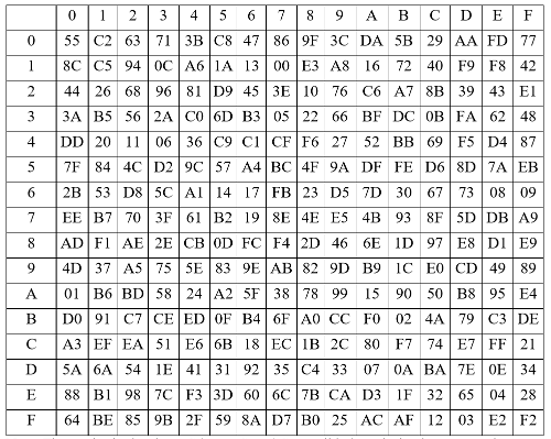
The Rijndael S-box
The S-box SR maps 8 bit to 8 bit. Here the input and output is presented in hexadecimal form
Let  be hexadecimal digits with
  , then the cell at the intersection of the
  row and the
  column contains the values for
  in hexadecimal form
For example 
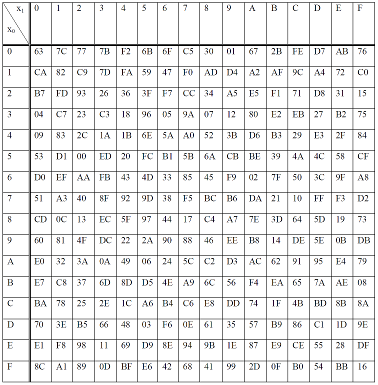
The S-box
The S-box maps 8 bit to 8 bit. Here the input is presented in hexadecimal form
Let be hexadecimal digits with  , then the cell at the intersection of the row and the column contains the values for in hexadecimal form
For example 
For API Documentation:
- See also
- ProtocolPP::jconfident
- ProtocolPP::jconfidentsa
- ProtocolPP::jmodes
- ProtocolPP::jsnow3g
- ProtocolPP::jsnowv
- ProtocolPP::jzuc
For Additional Documentation:
- See also
- jconfident
- jconfidentsa
- jmodes
- jsnow3g
- jsnowv
- jzuc
[1] By Serpent-linearfunction.png: User:Dakederivative work: Hydrox (talk) - Serpent-linearfunction.png, CC BY-SA 3.0, https://commons.wikimedia.org/w/index.php?curid=7437555
The source code contained or described herein and all documents related to the source code (herein called "Material") are owned by John Peter Greninger and Sheila Rocha Greninger. Title to the Material remains with John Peter Greninger and Sheila Rocha Greninger. The Material contains trade secrets and proprietary and confidential information of John Peter Greninger and Sheila Rocha Greninger. The Material is protected by worldwide copyright and trade secret laws and treaty provisions. No part of the Material may be used, copied, reproduced, modified, published, uploaded, posted, transmitted, distributed, or disclosed in any way without prior express written consent of John Peter Greninger and Sheila Rocha Greninger (both are required)
No license under any patent, copyright, trade secret, or other intellectual property right is granted to or conferred upon you by disclosure or delivery of the Materials, either expressly, by implication, inducement, estoppel, or otherwise. Any license under such intellectual property rights must be express and approved by John Peter Greninger and Sheila Rocha Greninger in writing
Licensing information can be found at www.protocolpp.com/license with use of the binary forms permitted provided that the following conditions are met:
- Redistributions in binary form must reproduce the above copyright notice, this list of conditions and the following disclaimer in the documentation and/or other materials provided with the distribution
- Any and all modifications must be returned to John Peter Greninger at GitHub.com https://github.com/jpgreninger/protocolpp for evaluation. Inclusion of modifications in the source code shall be determined solely by John Peter Greninger. Failure to provide modifications shall render this license NULL and VOID and revoke any rights to use of Protocol++®
- Commercial use (incidental or not) requires a fee-based license obtainable at www.protocolpp.com/shop
- Academic or research use requires prior written and notarized permission from John Peter and Sheila Rocha Greninger
Use of the source code requires purchase of the source code. Source code can be purchased at www.protocolpp.com/shop
- US Copyrights at https://www.copyright.gov/
- TXu002059872 (Version 1.0.0)
- TXu002066632 (Version 1.2.7)
- TXu002082674 (Version 1.4.0)
- TXu002097880 (Version 2.0.0)
- TXu002169236 (Version 3.0.1)
- TXu002182417 (Version 4.0.0)
- TXu002219402 (Version 5.0.0)
- TXu002272076 (Version 5.2.1)
- TXu002383571 (Version 5.4.3)
The name of its contributor may not be used to endorse or promote products derived from this software without specific prior written permission and licensing
THIS SOFTWARE IS PROVIDED BY THE COPYRIGHT HOLDER AND CONTRIBUTOR "AS IS" AND ANY EXPRESS OR IMPLIED WARRANTIES, INCLUDING, BUT NOT LIMITED TO, THE IMPLIED WARRANTIES OF MERCHANTABILITY AND FITNESS FOR A PARTICULAR PURPOSE ARE DISCLAIMED. IN NO EVENT SHALL THE COPYRIGHT OWNER OR CONTRIBUTORS BE LIABLE FOR ANY DIRECT, INDIRECT, INCIDENTAL, SPECIAL, EXEMPLARY, OR CONSEQUENTIAL DAMAGES (INCLUDING, BUT NOT LIMITED TO, PROCUREMENT OF SUBSTITUTE GOODS OR SERVICES; LOSS OF USE, DATA, OR PROFITS; OR BUSINESS INTERRUPTION) HOWEVER CAUSED AND ON ANY THEORY OF LIABILITY, WHETHER IN CONTRACT, STRICT LIABILITY, OR TORT (INCLUDING NEGLIGENCE OR OTHERWISE) ARISING IN ANY WAY OUT OF THE USE OF THIS SOFTWARE, EVEN IF ADVISED OF THE POSSIBILITY OF SUCH DAMAGE
The documentation for this class was generated from the following file:
- include/jconfident.h