#include "include/judp.h"
Detailed Description
User Datagram Protocol (UDP)
See https://en.wikipedia.org/wiki/User_Datagram_Protocol
This User Datagram Protocol (UDP) is defined to make available a datagram mode of packet-switched computer communication in the environment of an interconnected set of computer networks. This protocol assumes that the Internet Protocol (IP) [1] is used as the underlying protocol. This protocol provides a procedure for application programs to send messages to other programs with a minimum of protocol mechanism. The protocol is transaction oriented, and delivery and duplicate protection are not guaranteed. Applications requiring ordered reliable delivery of streams of data should use the Transmission Control Protocol (TCP) [2]
User Datagram Header Format [1]

Source Port
An optional field, when meaningful, it indicates the port of the sending process and may be assumed to be the port to which a reply should be addressed in the absence of any other information. If not used, a value of zero is inserted.
Destination Port
Has a meaning within the context of a particular internet destination address
Length
The length in octets of this user datagram including this header and the data (This means the minimum value of the length is eight)
Checksum
The 16-bit one’s complement of the one’s complement sum of a pseudo header of information from the IP header, the UDP header, and the data, padded with zero octets at the end (if necessary) to make a multiple of two octets
The pseudo header conceptually prefixed to the UDP header contains the source address, the destination address, the protocol, and the UDP length. This information gives protection against misrouted datagrams. This checksum procedure is the same as is used in TCP.
If the computed checksum is zero, it is transmitted as all ones (the equivalent in one’s complement arithmetic). An all zero transmitted checksum value means that the transmitter generated no checksum (for debugging or for higher level protocols that don’t care)
Checksum computation
The method used to compute the checksum is defined in RFC 768:
Checksum is the 16-bit one's complement of the one's complement sum of a pseudo header of information from the IP header, the UDP header, and the data, padded with zero octets at the end (if necessary) to make a multiple of two octets
In other words, all 16-bit words are summed using one's complement arithmetic. Add the 16-bit values up. Each time a carry-out (17th bit) is produced, swing that bit around and add it back into the least significant bit.[8] The sum is then one's complemented to yield the value of the UDP checksum field.
If the checksum calculation results in the value zero (all 16 bits 0) it should be sent as the one's complement (all 1s).
The difference between IPv4 and IPv6 is in the data used to compute the checksum.
IPv4 Pseudo Header
When UDP runs over IPv4, the checksum is computed using a "pseudo header" that contains some of the same information from the real IPv4 header. The pseudo header is not the real IPv4 header used to send an IP packet, it is used only for the checksum calculation.
IPv4 Pseudo Header Format [2]

- The source and destination addresses are those in the IPv4 header
- The protocol is that for UDP (see List of IP protocol numbers): 17 (0x11)
- The UDP length field is the length of the UDP header and data
- The field data is the transmitted data
UDP checksum computation is optional for IPv4. If a checksum is not used it should be set to the value zero.
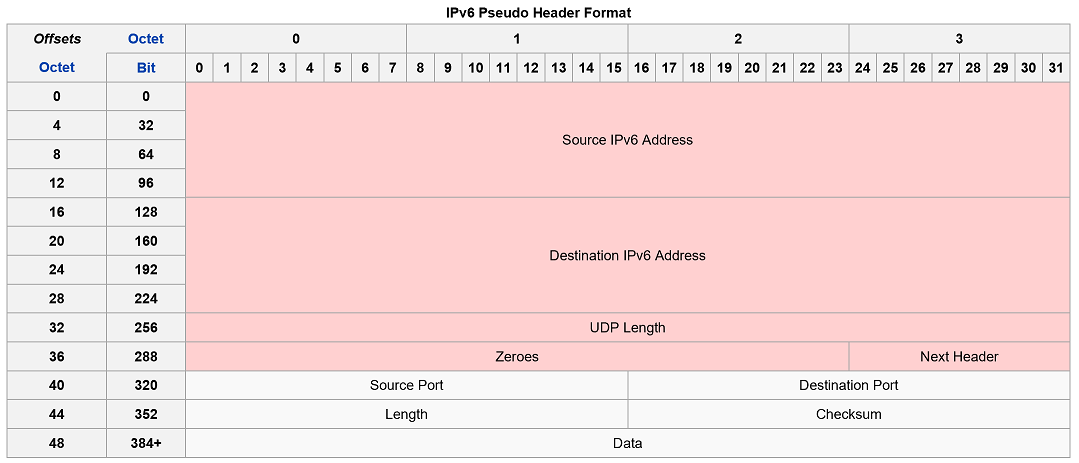
IPv6 Pseudo Header
When UDP runs over IPv6, the checksum is mandatory. The method used to compute it is changed as documented in RFC 2460:
Any transport or other upper-layer protocol that includes the addresses from the IP header in its checksum computation must be modified for use over IPv6 to include the 128-bit IPv6 addresses
When computing the checksum, again a pseudo header is used that mimics the real IPv6 header:
IPv6 Pseudo Header Format [3]

- The source address is the one in the IPv6 header
- The destination address is the final destination; if the IPv6 packet does not contain a Routing header, that will be the destination address in the IPv6 header; otherwise, at the originating node, it will be the address in the last element of the Routing header, and, at the receiving node, it will be the destination address in the IPv6 header
- The value of the Next Header field is the protocol value for UDP: 17
- The UDP length field is the length of the UDP header and data
Virtual eXtensible Local Area Network (VXLAN)
See rfc7348 for full details
Current Layer 2 networks use the IEEE 802.1D Spanning Tree Protocol (STP) to avoid loops in the network due to duplicate paths. STP blocks the use of links to avoid the replication and looping of frames. Some data center operators see this as a problem with Layer 2 networks in general, since with STP they are effectively paying for more ports and links than they can really use. In addition, resiliency due to multipathing is not available with the STP model
Newer initiatives, such as TRILL [RFC6325] and SPB [802.1aq], have been proposed to help with multipathing and surmount some of the problems with STP. STP limitations may also be avoided by configuring servers within a rack to be on the same Layer 3 network, with switching happening at Layer 3 both within the rack and between racks. However, this is incompatible with a Layer 2 model for inter-VM communication
A key characteristic of Layer 2 data center networks is their use of Virtual LANs (VLANs) to provide broadcast isolation. A 12-bit VLAN ID is used in the Ethernet data frames to divide the larger Layer 2 network into multiple broadcast domains. This has served well for many data centers that require fewer than 4094 VLANs. With the growing adoption of virtualization, this upper limit is seeing pressure. Moreover, due to STP, several data centers limit the number of VLANs that could be used. In addition, requirements for multi-tenant environments accelerate the need for larger VLAN limits
Multi-tenant Environments
Cloud computing involves on-demand elastic provisioning of resources for multi-tenant environments. The most common example of cloud computing is the public cloud, where a cloud service provider offers these elastic services to multiple customers/tenants over the same physical infrastructure
Isolation of network traffic by a tenant could be done via Layer 2 or Layer 3 networks. For Layer 2 networks, VLANs are often used to segregate traffic – so a tenant could be identified by its own VLAN, for example. Due to the large number of tenants that a cloud provider might service, the 4094 VLAN limit is often inadequate. In addition, there is often a need for multiple VLANs per tenant, which exacerbates the issue
A related use case is cross-pod expansion. A pod typically consists of one or more racks of servers with associated network and storage connectivity. Tenants may start off on a pod and, due to expansion, require servers/VMs on other pods, especially in the case when tenants on the other pods are not fully utilizing all their resources. This use case requires a "stretched" Layer 2 environment connecting the individual servers/VMs.
Layer 3 networks are not a comprehensive solution for multi-tenancy either. Two tenants might use the same set of Layer 3 addresses within their networks, which requires the cloud providerk to provide isolation in some other form. Further, requiring all tenants to use IP excludes customers relying on direct Layer 2 or non-IP Layer 3 protocols for inter VM communication
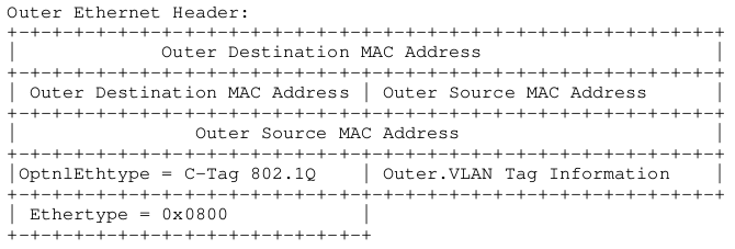
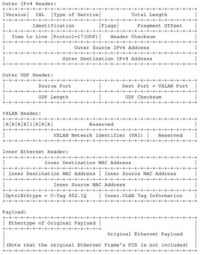
VXLAN (Virtual eXtensible Local Area Network) addresses the above requirements of the Layer 2 and Layer 3 data center network infrastructure in the presence of VMs in a multi-tenant environment It runs over the existing networking infrastructure and provides a means to "stretch" a Layer 2 network. In short, VXLAN is a Layer 2 overlay scheme on a Layer 3 network Each overlay is termed a VXLAN segment. Only VMs within the same VXLAN segment can communicate with each other. Each VXLAN segment is identified through a 24-bit segment ID, termed the "VXLAN Network Identifier (VNI)". This allows up to 16 M VXLAN segments to coexist within the same administrative domain
The VNI identifies the scope of the inner MAC frame originated by the individual VM. Thus, you could have overlapping MAC addresses across segments but never have traffic "cross over" since the traffic is isolated using the VNI. The VNI is in an outer header that encapsulates the inner MAC frame originated by the VM. In the following sections, the term "VXLAN segment" is used interchangeably with the term "VXLAN overlay network"
Due to this encapsulation, VXLAN could also be called a tunneling scheme to overlay Layer 2 networks on top of Layer 3 networks. The tunnels are stateless, so each frame is encapsulated according to a set of rules. The end point of the tunnel (VXLAN Tunnel End Point or VTEP) discussed in the following sections is located within the hypervisor on the server that hosts the VM. Thus, the VNI- and VXLAN-related tunnel / outer header encapsulation are known only to the VTEP – the VM never sees it (see Figure 1). Note that it is possible that VTEPs could also be on a physical switch or physical server and could be implemented in software or hardware One use case where the VTEP is a physical switch is discussed in Section 6 on VXLAN deployment scenarios


[1] http://microchip.wikidot.com/tcpip:tcp-vs-udp
[2] https://en.wikipedia.org/wiki/User_Datagram_Protocol
[3] https://en.wikipedia.org/wiki/User_Datagram_Protocol
For API Documentation:
For Additional Documentation:
The source code contained or described herein and all documents related to the source code (herein called "Material") are owned by John Peter Greninger and Sheila Rocha Greninger. Title to the Material remains with John Peter Greninger and Sheila Rocha Greninger. The Material contains trade secrets and proprietary and confidential information of John Peter Greninger and Sheila Rocha Greninger. The Material is protected by worldwide copyright and trade secret laws and treaty provisions. No part of the Material may be used, copied, reproduced, modified, published, uploaded, posted, transmitted, distributed, or disclosed in any way without prior express written consent of John Peter Greninger and Sheila Rocha Greninger (both are required)
No license under any patent, copyright, trade secret, or other intellectual property right is granted to or conferred upon you by disclosure or delivery of the Materials, either expressly, by implication, inducement, estoppel, or otherwise. Any license under such intellectual property rights must be express and approved by John Peter Greninger and Sheila Rocha Greninger in writing
Licensing information can be found at www.protocolpp.com/license with use of the binary forms permitted provided that the following conditions are met:
- Redistributions in binary form must reproduce the above copyright notice, this list of conditions and the following disclaimer in the documentation and/or other materials provided with the distribution
- Any and all modifications must be returned to John Peter Greninger at GitHub.com https://github.com/jpgreninger/protocolpp for evaluation. Inclusion of modifications in the source code shall be determined solely by John Peter Greninger. Failure to provide modifications shall render this license NULL and VOID and revoke any rights to use of Protocol++®
- Commercial use (incidental or not) requires a fee-based license obtainable at www.protocolpp.com/shop
- Academic or research use requires prior written and notarized permission from John Peter and Sheila Rocha Greninger
Use of the source code requires purchase of the source code. Source code can be purchased at www.protocolpp.com/shop
- US Copyrights at https://www.copyright.gov/
- TXu002059872 (Version 1.0.0)
- TXu002066632 (Version 1.2.7)
- TXu002082674 (Version 1.4.0)
- TXu002097880 (Version 2.0.0)
- TXu002169236 (Version 3.0.1)
- TXu002182417 (Version 4.0.0)
- TXu002219402 (Version 5.0.0)
- TXu002272076 (Version 5.2.1)
- TXu002383571 (Version 5.4.3)
The name of its contributor may not be used to endorse or promote products derived from this software without specific prior written permission and licensing
THIS SOFTWARE IS PROVIDED BY THE COPYRIGHT HOLDER AND CONTRIBUTOR "AS IS" AND ANY EXPRESS OR IMPLIED WARRANTIES, INCLUDING, BUT NOT LIMITED TO, THE IMPLIED WARRANTIES OF MERCHANTABILITY AND FITNESS FOR A PARTICULAR PURPOSE ARE DISCLAIMED. IN NO EVENT SHALL THE COPYRIGHT OWNER OR CONTRIBUTORS BE LIABLE FOR ANY DIRECT, INDIRECT, INCIDENTAL, SPECIAL, EXEMPLARY, OR CONSEQUENTIAL DAMAGES (INCLUDING, BUT NOT LIMITED TO, PROCUREMENT OF SUBSTITUTE GOODS OR SERVICES; LOSS OF USE, DATA, OR PROFITS; OR BUSINESS INTERRUPTION) HOWEVER CAUSED AND ON ANY THEORY OF LIABILITY, WHETHER IN CONTRACT, STRICT LIABILITY, OR TORT (INCLUDING NEGLIGENCE OR OTHERWISE) ARISING IN ANY WAY OUT OF THE USE OF THIS SOFTWARE, EVEN IF ADVISED OF THE POSSIBILITY OF SUCH DAMAGE
The documentation for this class was generated from the following file:
- include/judp.h